Maneuverable, compact vehicles are vital, especially in snow-covered and forested areas. In some countries, such as the USA, Canada, and Japan, this problem is solved by producing compact machines like snowmobiles. Our industry has also started producing such equipment: snowmobiles “Buran”, “Amurets” and others have appeared. However, these machines are more for recreation; they don’t even have an insulated cabin.
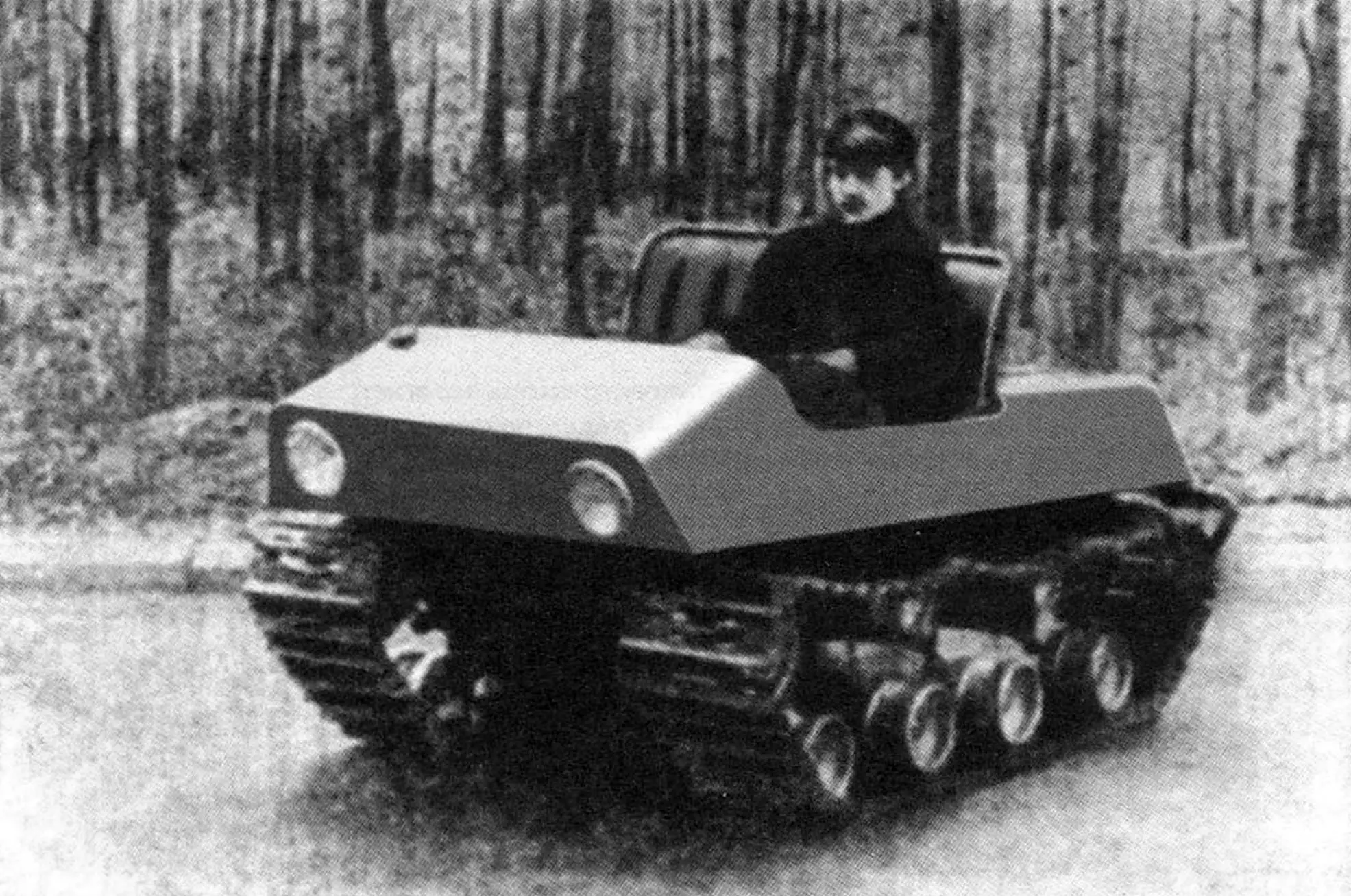
In our laboratory for designing compact equipment, we built a small but “working” machine – a micro all-terrain vehicle for a forester (see photo). It combines the advantages of large tracked all-terrain vehicles – high cross-country capability and maneuverability, the possibility of having an insulated cabin, necessary power and speed – with small dimensions and weight.
All this makes the all-terrain vehicle convenient for use by forestry workers in hard-to-reach areas of our country.
Design Description
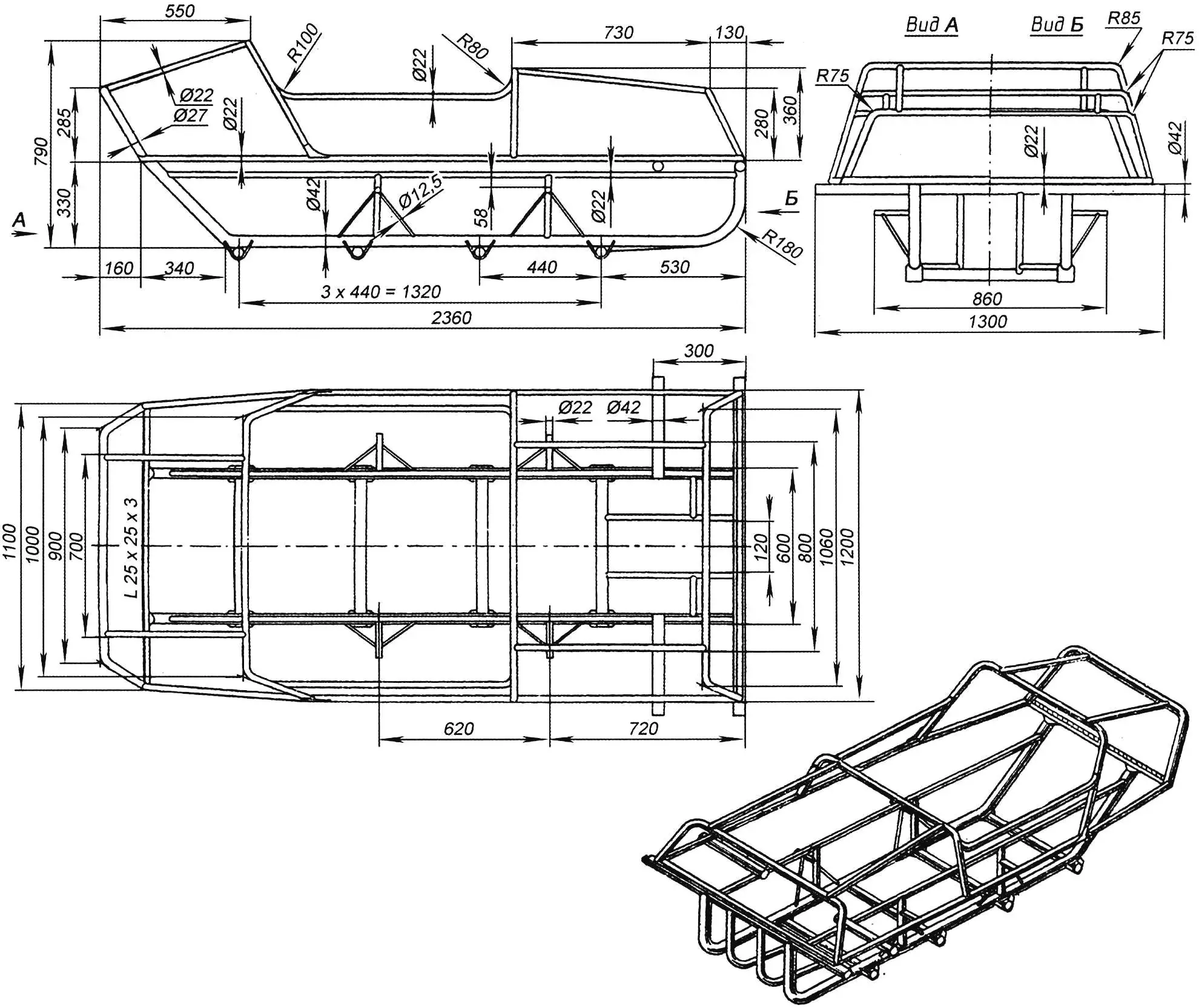
The frame (Fig. 2) of closed rectangular shape consists of two longitudinal stringers made of 42 mm diameter pipe, to which four torsion suspension housings from the front axle of the SZA motorized wheelchair and pipes with diameters of 22 and 27 mm are welded from below, repeating the body silhouette.
The body is made of sheet steel with a thickness of 0.5 – 0.8 mm. For simplicity and convenience of its manufacture, templates were first cut out of thin cardboard. Then blanks were made from them, which were fixed by electric or gas welding to the body frame pipes.
At the front of the frame, mechanisms for track tensioning are installed (Fig. 1, B – B).
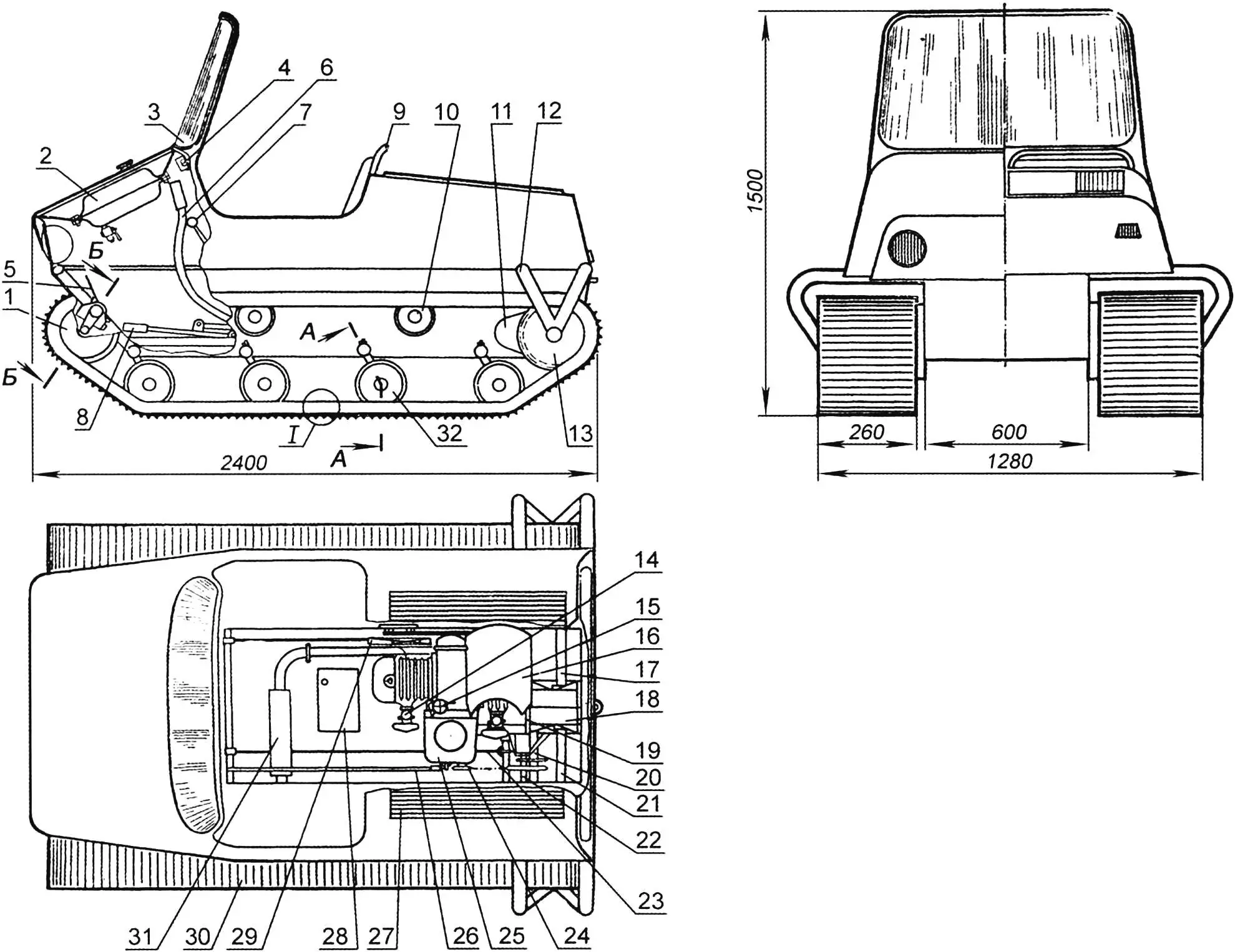
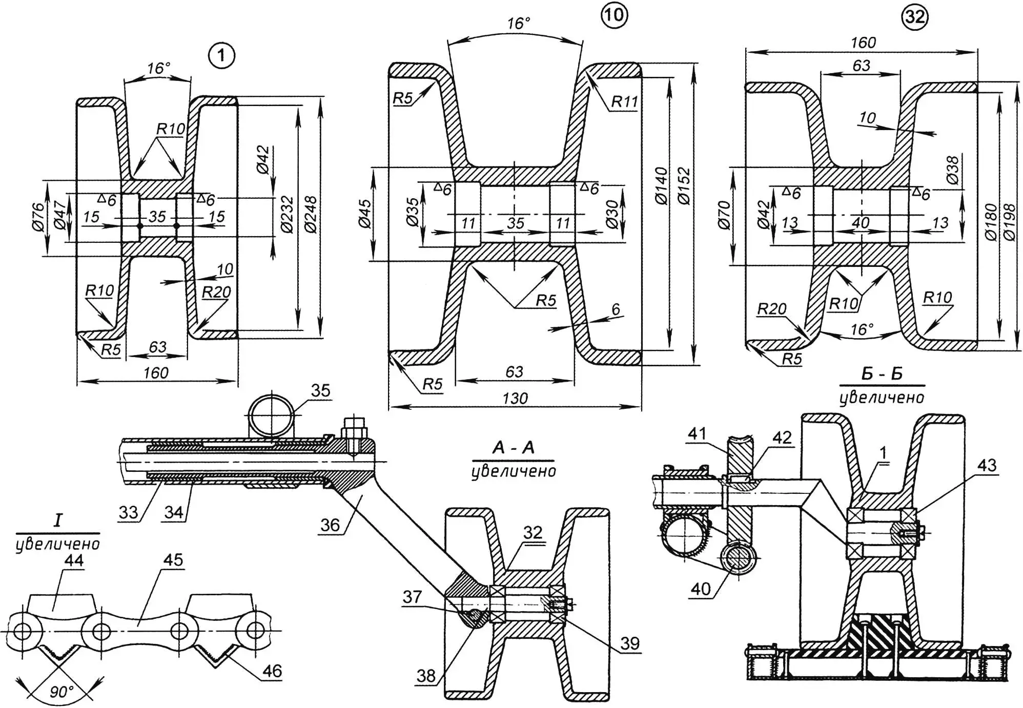
1 – tension roller; 2 – fuel tank; 3 – windshield; 4 – instrument panel; 5 – gas pedal; 6 – brake lever; 7 – gear shift handle; 8 – kickstarter lever; 9 – seat; 10 – upper support roller; 11 – band brake housing; 12 – half-axle bracket; 13 – drive sprocket; 14 – carburetor; 15 – fuel pump; 16 – fan housing; 17 – half-axle; 18 – differential; 19 – M-62 engine; 20 – driven shaft; 21 – half-axle; 22 – intermediate shaft; 23 – brake rod; 24 – engine drive sprocket; 25 – gearbox; 26 – kickstarter rod; 27 – louvers; 28 – battery; 29 – fan (housing removed); 30 – track; 31 – muffler; 32 – support roller; 33 – bushing; 34 – torsion housing; 35 – frame; 36 – torsion lever; 37 – locking bolt; 38 – roller axis; 39 – bearing No. 302; 40 – worm for track tensioning; 41 – worm wheel; 42 – key; 43 – bearing No. 303; 44 – belt guide protrusion; 45 – chain; 46 – ground grip
In the front part of the body under the hood is located the fuel tank. Fuel is supplied to the carburetors by gravity. The instrument panel is from a UAZ-452 vehicle. It has an ignition lock, fuel level indicator in the fuel tank, engine temperature indicator, turn signal lights.
The windshield made of organic glass is fixed in a tubular frame with sealing rubber.
In winter and bad weather, installation of a canvas cabin is provided, which is stretched over a removable frame made of duralumin pipes with a diameter of 18 mm. The driver’s cabin heating is provided by the muffler, which is attached to the engine exhaust pipe using flanges. In winter, it is located under the driver’s feet, and in summer, thanks to the flange mounting, it is turned in the opposite direction and routed under the right track. Additional heating is also provided by warm air from the forced cooling fans of the engine.
The engine is a modernized M-62 “Ural”. Located in the rear part of the body. Its conversion for forced air cooling is as follows: a shaft is extended through the front engine cover (Fig. 3, pos. 13), which is welded by electric welding to the small timing gear. A bearing housing No. 204 is welded to the front engine cover by argon-arc welding, which is the second support of the fan drive shaft. In the absence of argon-arc welding, the bearing housing can be secured with M6 bolts through a gasket to avoid oil leakage from the engine crankcase. The fan drive shaft together with the small timing gear is fixed on the engine crankshaft with a key and M8 bolt.
A double-groove pulley (Fig. 3, pos. 6) is mounted on the drive shaft, which transmits rotation to two driven pulleys using V-belts. Axial eight-blade fans are attached to them. The pulleys are located directly in front of the engine cylinders and are fixed on brackets that are welded to the body frame.
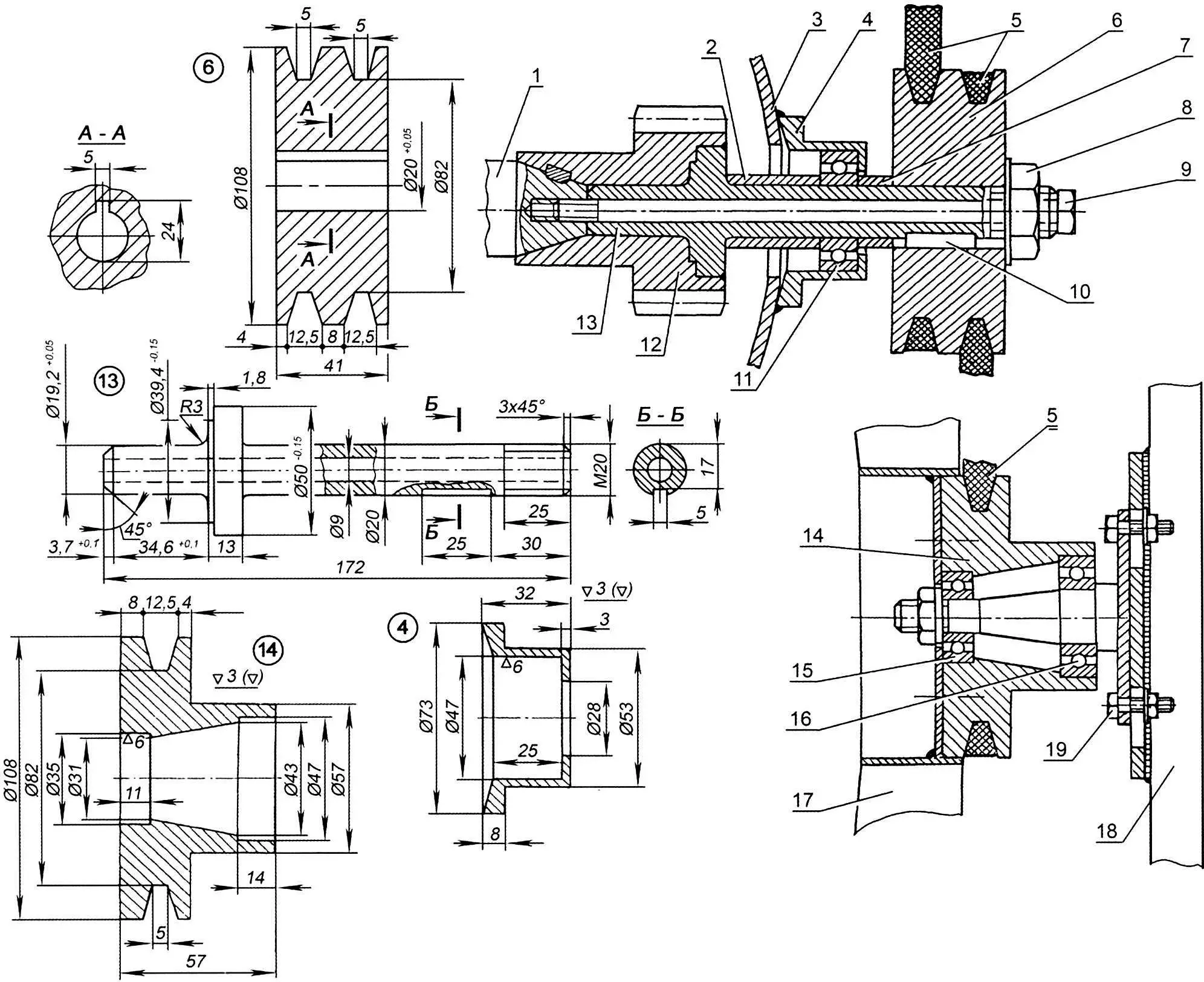
1 – engine crankshaft; 2 – spacer bushing; 3 – front engine cover; 4 – bearing housing; 5 – V-belt; 6 – double-groove pulley; 7 – spacer bushing; 8 – pulley mounting nut; 9 – M8 bolt; 10 – key; 11 – bearing No. 204; 12 – small timing gear; 13 – fan drive shaft; 14 – pulley; 15 – bearing No. 202; 16 – bearing No. 204; 17 – eight-blade fan; 18 – frame; 19 – M10 bolt
The air flow is directed to the cylinders using housings (Fig. 1, pos. 16, the housing of the other fan is not shown). After cooling the cylinder, the air flow is discharged outside through the louvers of the engine compartment floor, which are located along the direction of travel of the all-terrain vehicle. In winter, the floor louvers are closed, and air enters the cabin. Air intake for engine cooling is through louvers in the upper covers of the engine compartment.
Engine starting is done manually, using a lever located on the left side of the driver’s seat. The lever is connected by a rod to a shortened kickstarter pedal.
The all-terrain vehicle uses a chain drive from the engine to the differential. This is due to the structural location of the engine on the all-terrain vehicle frame and the use of a differential from the S3A motorized wheelchair, adapted for chain drive.
The conversion of the M-62 “Ural” engine for chain drive of the gearbox secondary shaft is as follows: the cardan fork is removed and the sprocket seat (from Izh-56 motorcycle) is machined, having a pitch of 15.88 mm and number of teeth – 18. The sprocket is welded to the cardan fork by electric welding.
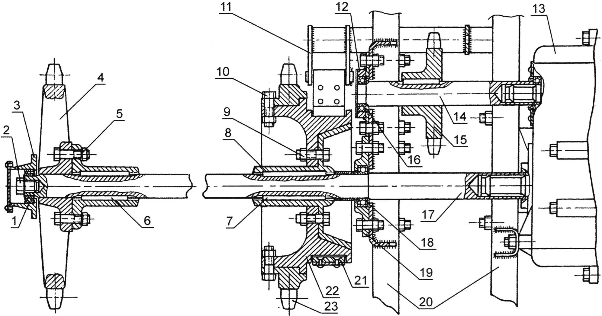
1 – bearing No. 205; 2 – M14 screw; 3 – external half-axle support; 4 – drive sprocket; 5 – M10 bolt; 6,7 – keys; 8 – brake pulley hub; 9,10 – M10 bolts; 11 – band brake lever; 12 – bearing housing; 13 – differential (S3A); 14 – differential shaft; 15 – differential shaft sprocket; 16 – bearing No. 205; 17 – half-axle; 18 – bearing No. 206; 19 – bearing housing; 20 – frame; 21 – band brake; 22 – brake pulley; 23 – drive sprocket
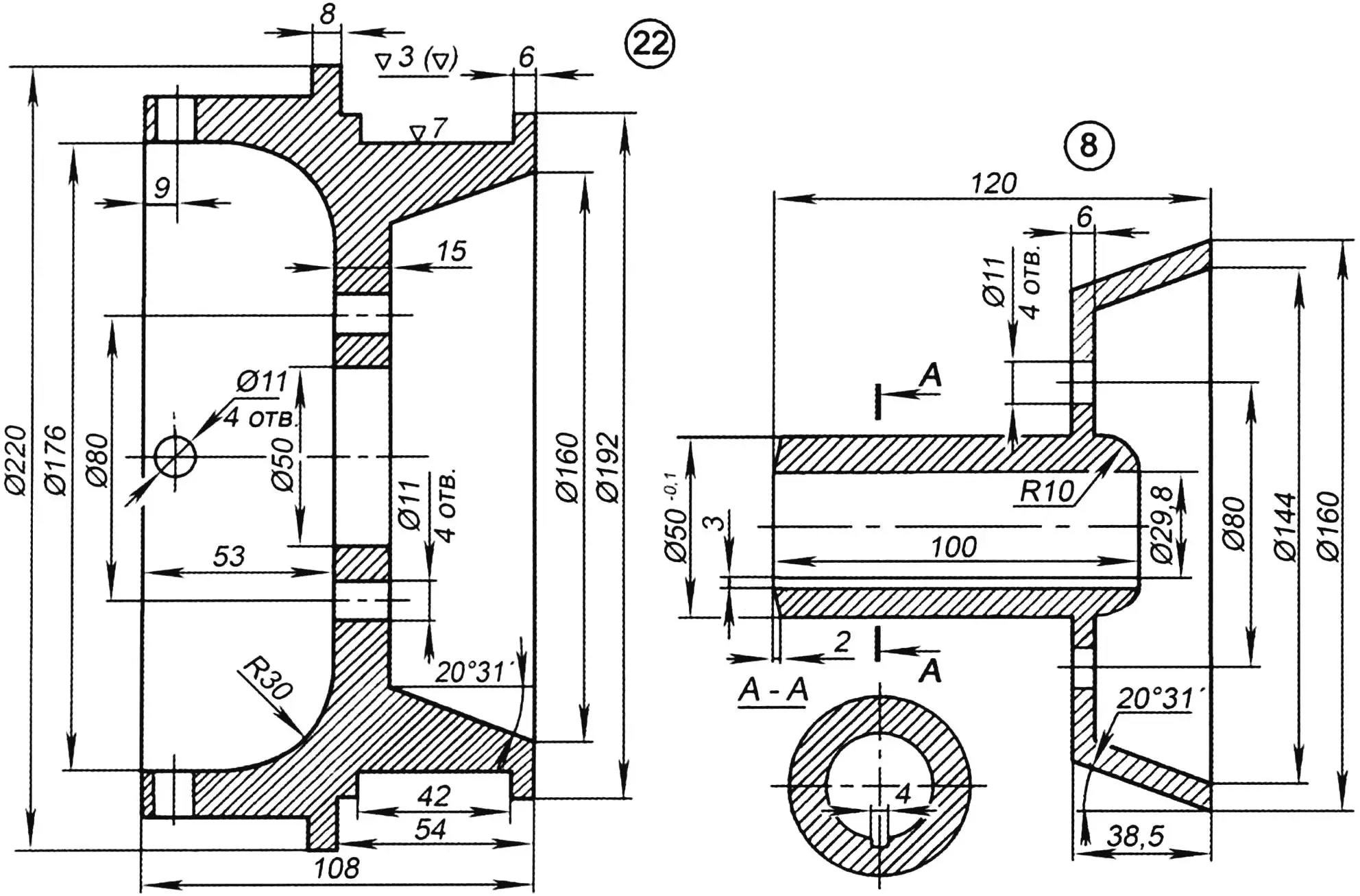
During testing of the all-terrain vehicle, it became necessary to install a reduction intermediate chain reducer with a gear ratio of 3. This made it possible to reduce the maximum speed to 50 km/h and increase the traction force on the tracks. Rotation from the reducer to the differential is transmitted by chain drive. Thus, the torque is transmitted from the engine to the reducer, then to the differential shaft (Fig. 4) and further to the half-axles. Two sprockets are attached to them, having a pitch of 37 mm and number of teeth – 26 (Fig. 4, pos. 4, 23). The sprockets drive the tracks. Since the half-axle significantly protrudes beyond the support on the frame and can bend under load, its outer end has an additional support in the form of a bracket fixed to the body frame.
The all-terrain vehicle has four forward speed gears and the same number in reverse. Their shifting, as well as reversing the all-terrain vehicle, are done with one lever taken from a UAZ-452 vehicle.
Turning the all-terrain vehicle is accomplished by braking one of the two differential half-axles. When one track slows down, the other begins to move at double speed, as if running ahead: the all-terrain vehicle turns.
For braking the differential half-axles, a band brake is used (Fig. 4, pos. 21), which consists of a brake pulley attached with M10 bolts to a hub sitting on the half-axle, and a metal band 38 mm wide. Friction linings with dimensions of 40x70x6 mm are attached to it with copper or aluminum rivets. When operating, the band brake should cover approximately three-quarters of its pulley. One end of the band is attached to a bracket welded to the frame, the other is pivotally connected to the drive lever (Fig. 4, pos. 11) of the band brake located in the driver’s cabin.
The all-terrain vehicle uses two control pedals: gas and clutch. There is no brake pedal, as it is enough to pull both levers toward yourself, having first depressed the clutch, and the tracks brake, and the all-terrain vehicle stops.
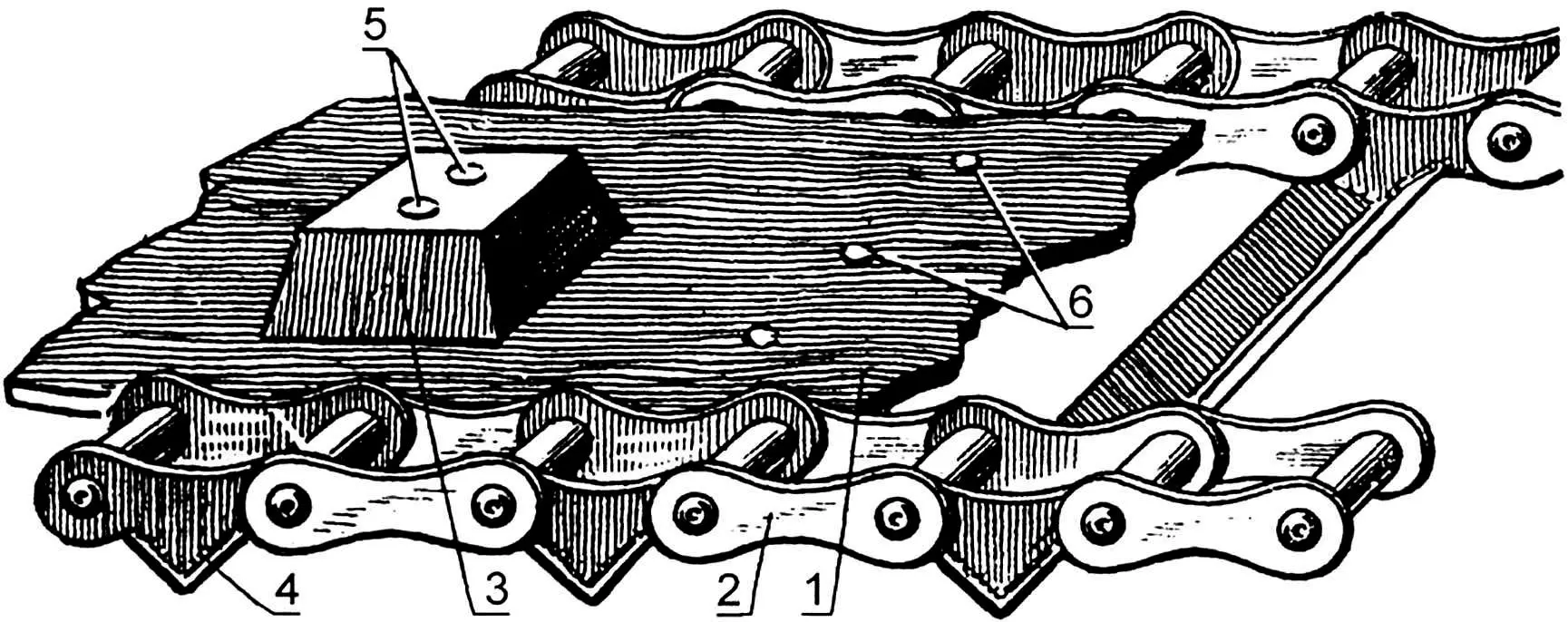
1 – conveyor belt; 2 – chain; 3 – guide protrusion; 4 – ground grip; 5,6 – rivets
The tracks are rubber-metal, with two parallel chains with a pitch of 37 mm (Fig. 5) from agricultural machinery conveyors. The existing protrusions on the chain are processed to the shape of ground grips made of steel angle 20x20x3. A rubber cord belt from a conveyor with a thickness of 7 mm is attached to them with rivets with a diameter of 6 mm.
For guiding the movement of rollers, rubber protrusions (Fig. 5, pos. 3) from a V-belt (profile “E” GOST 1284-57) are used, which are attached to the belt with rivets with a diameter of 8 mm, passing through the ground grip and welded to its outer side.
When designing the track, it must be taken into account that the middle of the rubber belt thickness should lie exactly on the line connecting the centers of the chain rivets. Otherwise, the belt experiences deformation, working in tension or compression, which leads to its premature wear.
Hardened chains, quality welding, strong cord belt create a light and reliable track, and its sufficient width determines the specific ground pressure at full load within 70 g/cm2. The all-terrain vehicle runs well on loose snow, mud, on dry ground and asphalt – almost silently, without the usual clanking of tracks.
Brief Technical Data
Maximum speed, km/h 50
Engine M-62 “Ural” with forced cooling
Maximum specific ground pressure, g/cm2 70
Curb weight, kg 350
“Modelist-Konstruktor” No. 6’2012, A. NALIMOV, E. STEPANENKO
Recommend to read
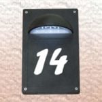 BACKLIGHT HOUSE NUMBERS
Lighting house number and street name in rural areas - is not an empty whim, but a basic necessity. In dark time of day the postman will be able to deliver a telegram, and RAM service...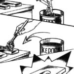 CANDLE AGAINST RUST
Much easier to remove rust from any parts, if its surface is pre-treated with a special compound which is easy to make at home. To do this, simply chop the wax (i.e. candle) in a small...
