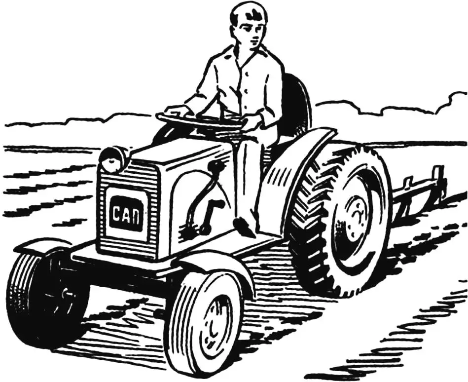
This mini-tractor was built in the Pavlov family’s amateur design bureau: under the head of the family, Valery Vasilyevich, it was assembled by his sons Sergey and Andrei. All three are long-time regular readers of «Modelist-Konstruktor» magazine.
The compact tractor, named SAP (S. and A. Pavlov) by its makers, was developed as a universal agricultural machine — for soil work and transport. It can plow, cultivate, harrow, and tow a cart with a load or a small tank of about 100 L for watering a garden plot.
The machine proved very successful — it is economical, maneuverable, and has high cross-country ability. It has eight gears — four forward and four reverse. Maximum speed is 37 km/h.
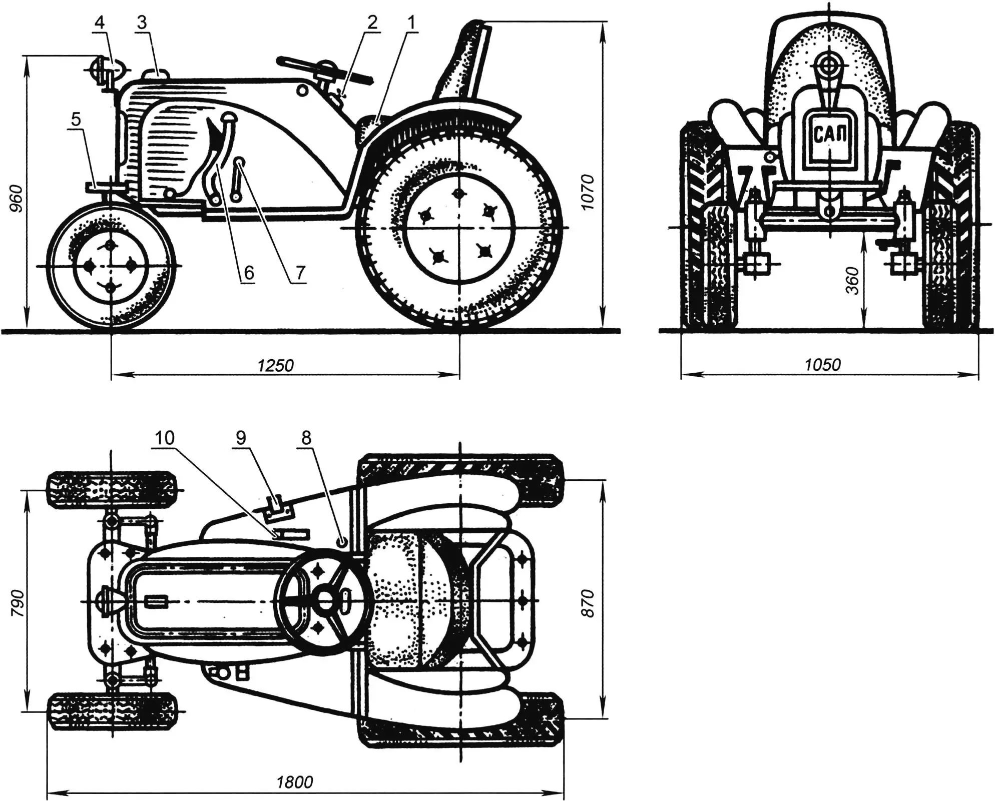
1 — driver’s seat; 2 — switch panel; 3 — hood cover handle; 4 — lighting lamp; 5 — front bumper; 6 — gearshift and clutch levers; 7 — kick-starter lever; 8 — reverse lever; 9 — brake pedal; 10 — throttle pedal
The mini-tractor frame is welded and shaped like a “horseshoe” bent from thick-walled 28 mm drill pipe, two angle-iron cross members, and ordinary 50 mm pipe. Two shaped steel plates at the rear mount intermediate sprockets. Using parts from the T-200 moped frame simplified engine installation and hood panel mounting.
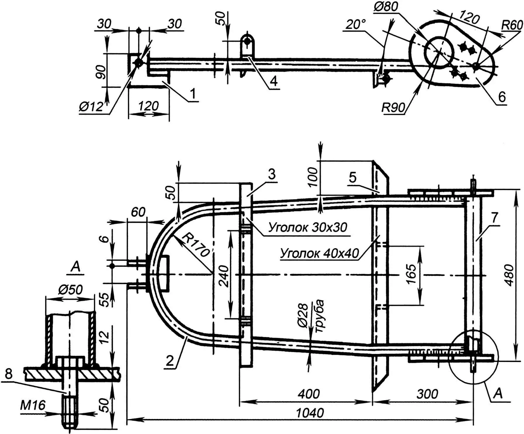
1 — engine mounting assembly; 2 — “horseshoe” (28 mm steel drill pipe); 3 — cross member (30×30 mm steel angle); 4 — bracket; 5 — cross member (40×40 mm steel angle); 6 — shaped plate for drive shaft mounting (12 mm steel plate); 7 — cross member (50 mm steel pipe); 8 — M16 bolt
Front axle. Its basis is a beam welded from 42 mm tubes in an H shape. Weld areas are reinforced with steel gussets. Bronze bushings are pressed into the spindle bushings. The joint between the front axle and frame consists of two gussets with a steel sleeve between them.
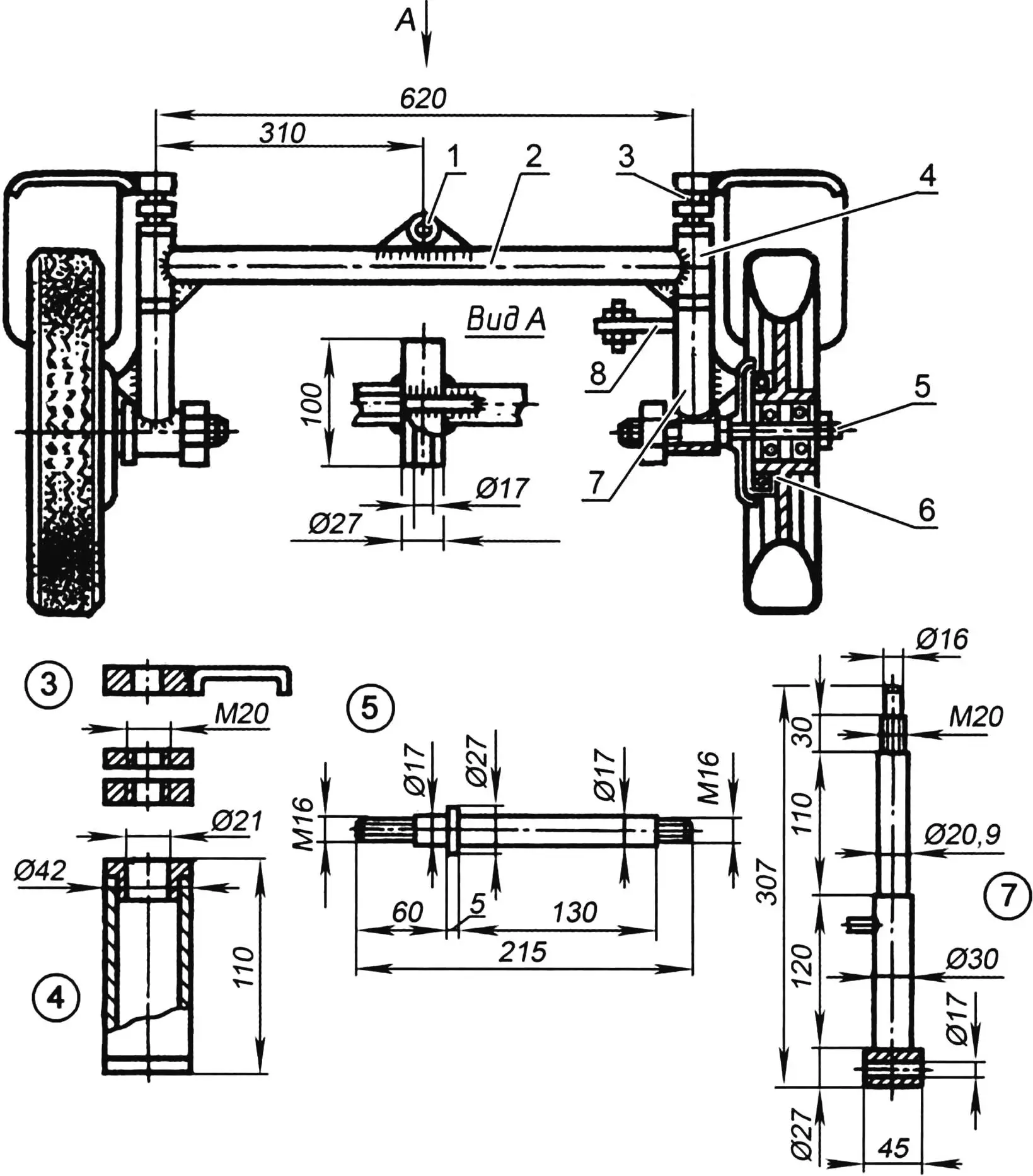
1 — front axle hinge assembly; 2 — front axle beam; 3 — front mudguard bracket; 4 — spindle bushing; 5 — half-shaft; 6 — front wheel hub with brake;
7 — spindle; 8 — steering lever
The steering knuckle is a turned stepped shaft with a welded steel sleeve (the front half-shaft fits into it). The steering trapezoid levers are pedals from a Riga moped.
Steering. Its core is a steering gearbox — a bevel-gear reducer (ratio 1:3) from a Druzhba chainsaw. The smaller gear is linked to the steering wheel; the larger shaft carries a pitman arm, and force is transmitted via a drag link from the pitman to a lever welded to the left spindle.
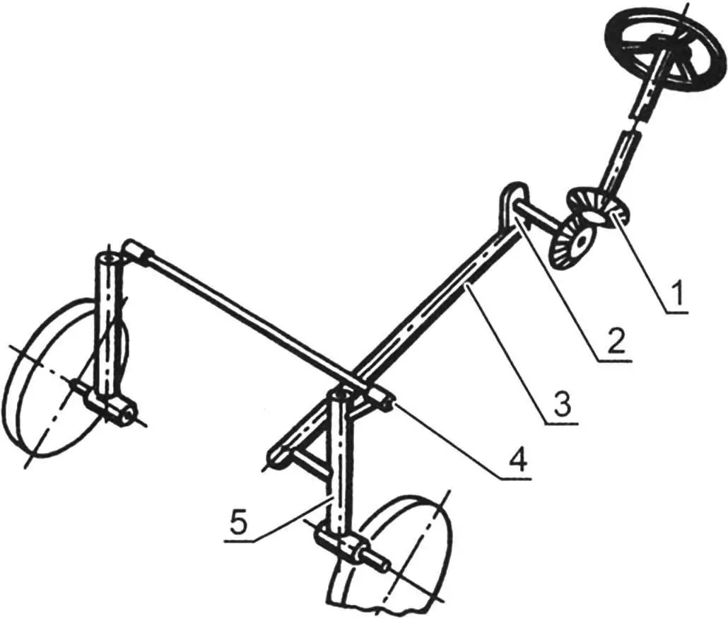
1 — steering gearbox; 2 — pitman arm; 3 — drag link; 4 — tie rod; 5 — steering knuckle
Transmission. Torque from the engine drive sprocket is transmitted by a bush-roller chain to the main differential with a reverse unit (from an S3D moped cart) and then to the hubs on the wheel half-shafts.
Rear axle. It is the most complex assembly on the mini-tractor, so its layout deserves a closer look. It is built mainly from scrapped car parts; the main task was to combine them as effectively as possible.
Wheel hubs are from a GAZ-69. To mount driven sprockets, stock studs were replaced with bolts and wheel disc mounting seats were modified accordingly. To make the rear axle more compact, the discs were flipped — the inner side became the outer side.
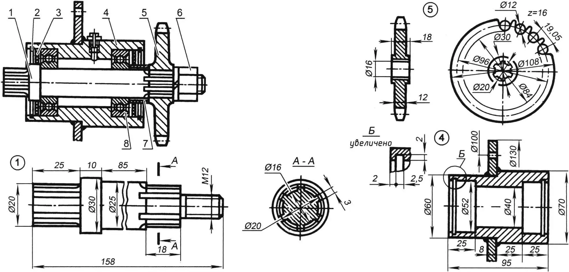
1 — drive shaft; 2 — retaining ring; 3 — oil seal; 4 — drive shaft mounting housing; 5 — drive sprocket; 6 — nut; 7 — bushing; 8 — ball bearing No. 205
Rear wheel brake drums are from a VP-150 moped. Five 10 mm holes were drilled for bolting to the wheel hub. Driven sprockets mount directly on the brake drums.
The brake shoe housing is from a Tourist moped. For mounting to the bearing housing, its central hole was enlarged to 52 mm and three 10 mm holes were drilled.
The brake shoe housing bushing and the assembly that mounts the half-shaft to the frame were made in-house.
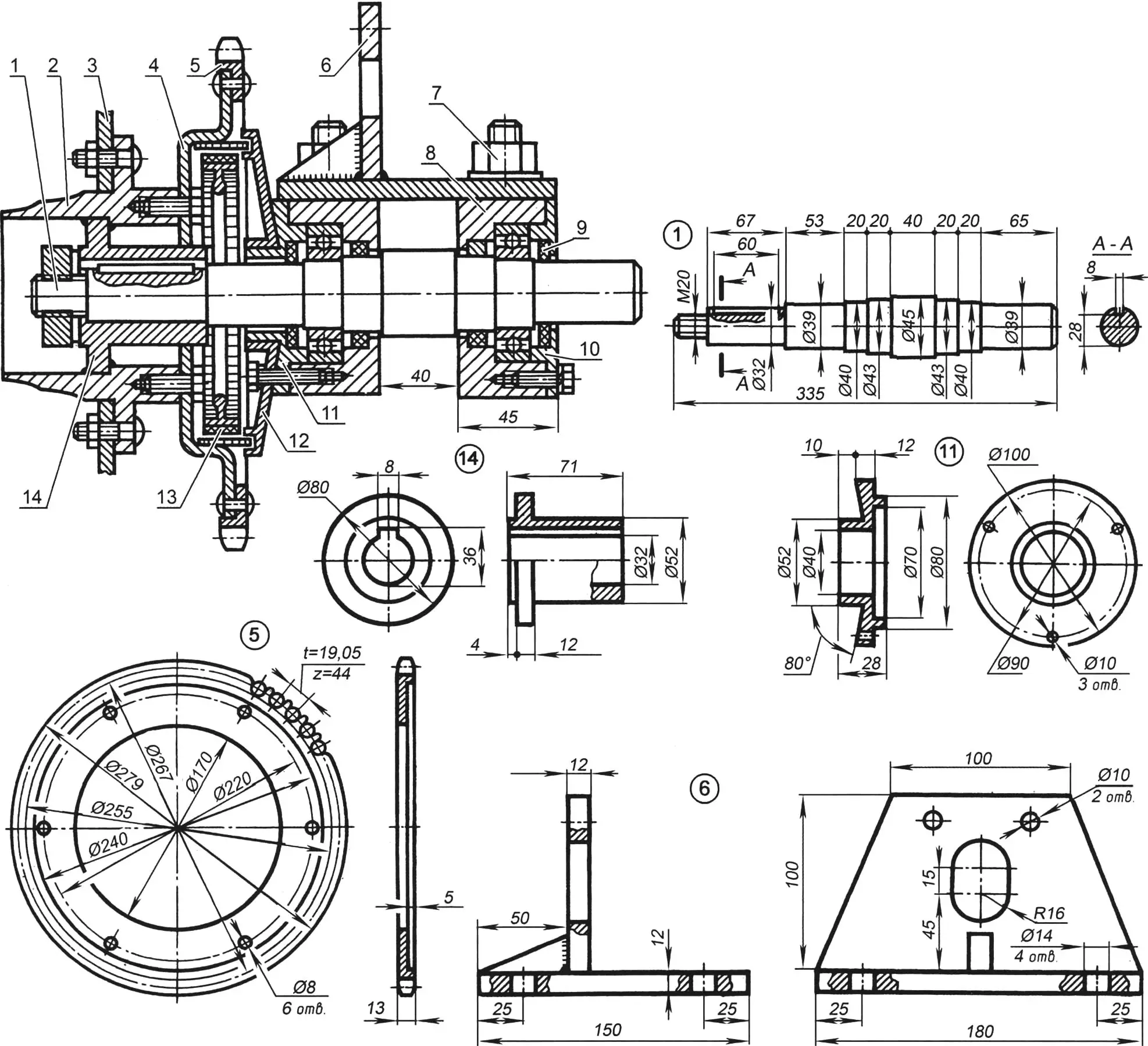
1 — half-shaft; 2 — wheel hub (from GAZ-69); 3 — wheel disc (from GAZ-60 or UAZ-469); 4 — brake drum (from Vyatka VP-150 moped); 5 — driven sprocket; 6 — half-shaft mounting plate; 7 — bolt with nut (bearing housing mount); 8 — bearing housing; 9 — oil seal; 10 — bearing housing cover; 11 — bushing; 12 — brake shoe housing; 13 — brake shoe; 14 — flange
The tractor’s most complex and critical parts and assemblies are shown in the figures.
The mini-tractor was used for many years without accidents or notable breakdowns. It worked successfully coupled with both a two-wheel trailer and a plow. An ice auger can be fitted without major difficulty.
The tractor has good mobility not only in summer but in winter: for deep snow, the front wheels are replaced with skis. The trailer is transformed the same way — from a two-wheel cart to a two-ski sled.
«Modelist-Konstruktor» No. 11’2013
Recommend to read
 RUBBER-ENGINE CHAMPIONS
The attention of all the adherents of the popular throughout the world class Ф1Б — rezinomotornaya expense of building a traditional model — we offer unusual today as on the content...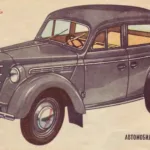 MOSKVICH 400
He appeared on the streets of the capital shortly after the war, in 1947. At first glance the design of the car "Moskvin-400" was not fundamental innovations. Its main advantage was a...
