Every motorist knows how difficult it can sometimes be to start a car engine on a winter morning after a long standstill. However, a relatively simple device powered from a 220 V AC mains supply will make this task much easier. The device consists of two parts (Fig. 1): one is a mains power supply (12—14 V); the second part is mounted in the car’s engine compartment. They are connected to each other by means of a special connector.
In the engine compartment, a board is secured with a bracket (Fig. 2), on which button SB1 (for cranking and starting the engine), switch SA1 “battery — mains”, and connector plug X1 (for connection to the power supply) are mounted.
The device provides cranking of the engine crankshaft, as well as starting the engine with the ignition key or button SB1 with the ignition switched on. At the same time, the car battery receives energy from the power supply.
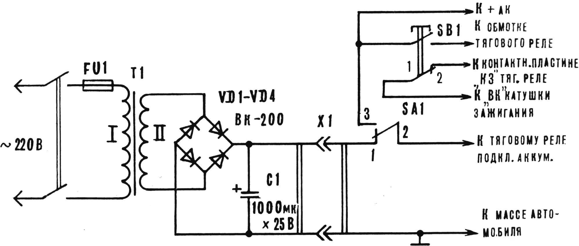
Let us consider the operation of the device using a VAZ-2101 car as an example. We connect the power supply to the onboard network using connector X1 (Fig. 1). We set switch SA1 to the “mains” position and connect the power supply itself to the 220 V mains. We turn the ignition key to the “off” position. By pressing button SB1, we crank the engine crankshaft. In this case, power from the battery through the contacts of button SB1 is supplied to the solenoid relay. Power from the supply through contacts 1—2 of switch SA1 goes to the solenoid relay and then, through the closed contacts of the solenoid relay, to the starter winding.
The engine is started with the ignition key as usual. With the ignition switched on, starting is also carried out by pressing button SB1.
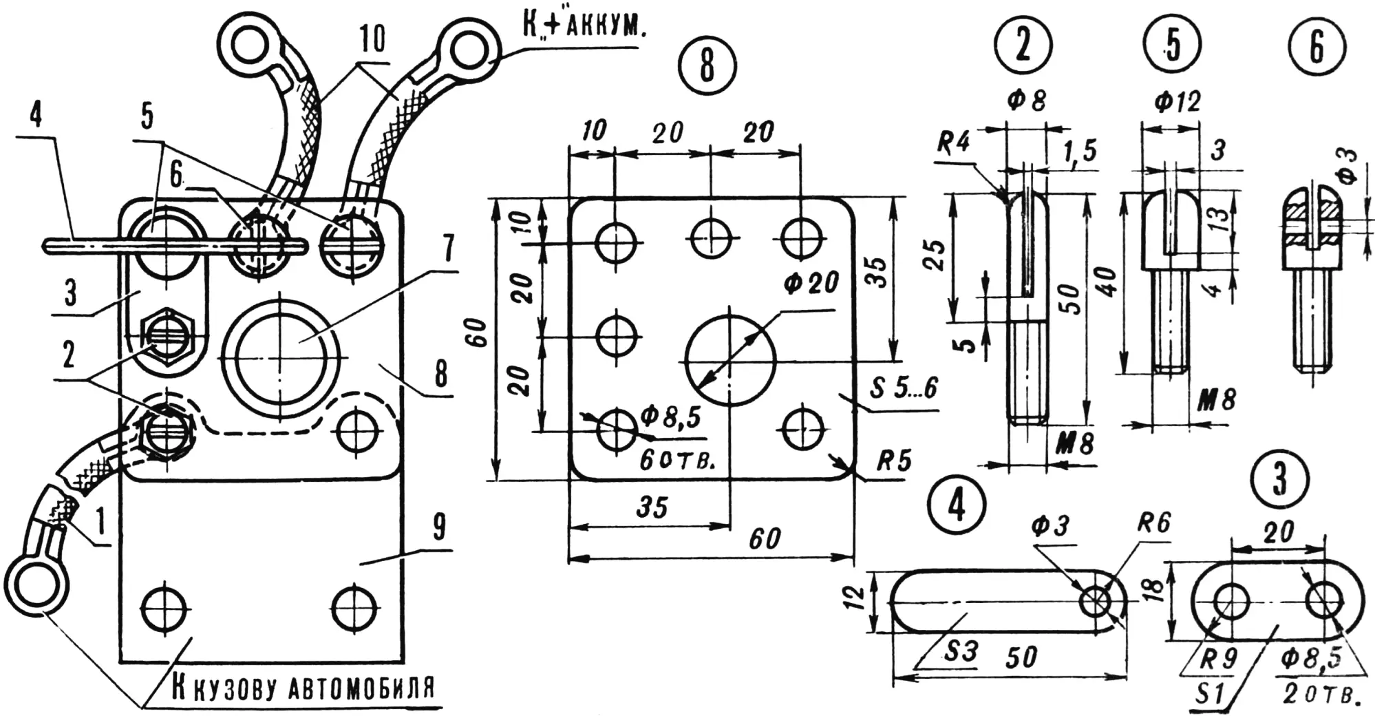
1, 10 — connecting wires, 2 — pins, 3 — jumper, 4 — switch lever, 5, 6 — switch contacts, 7 — button, 8 — base, 9 — mounting bracket.
When using the device on Moskvich-2140 and Zaporozhets cars, contacts 1—2 of button SB1 come into operation, preventing current from the power supply from entering the car’s ignition system while the solenoid relay is operating. The wire connecting the “KZ” contact plate on the solenoid relay and the “VK” terminal of the ignition coil must be disconnected. Everything else proceeds as described above.
After finishing work, the device is disconnected from the mains and from the car, and switch SA1 is set to the “battery” position.
Transformer T1 is a modified LATR-1M autotransformer. The modification is as follows. The winding is divided into two equal parts in terms of the number of turns. Both halves are connected in parallel and 45—50 turns of Ø 1.5 mm wire are added. This will be the mains winding. After laying an insulation layer, winding II is wound, consisting of 15 turns of wire with a cross-section of 40—50 mm2.
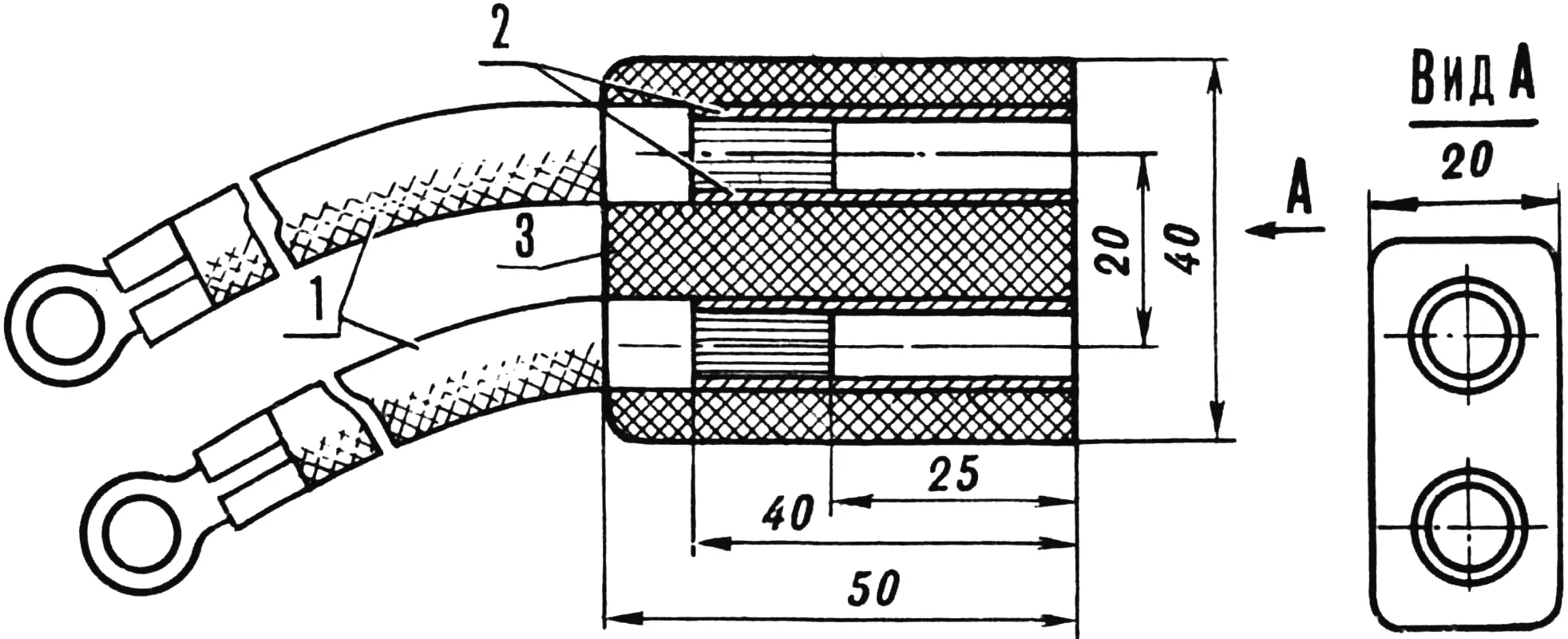
1 — connecting wires, 2 — tube Ø 10 mm, 3 — housing.
The diodes are VK-200 (or others rated for rectified current of at least 200 A) and are mounted on a textolite board without heat sinks.
Connector X1 is homemade. The socket housing (Fig. 3) is made of textolite or another insulating material. Sockets (a copper tube Ø 10×1 mm) are pressed or glued into the housing and connecting wires are soldered to them. The plug is mounted on the board (Fig. 2). The “battery — mains” switch is also homemade. Its design can be seen in the same drawing.
The wires supplying the starter must have a cross-section of 30—40 mm2 and be as short as possible. Capacitor C1 is optional.
«M-K» 10’91, L. VOVK, Sharivka village, Kharkiv region.
Recommend to read
 THE GYM IN YOUR BEDROOM
"Lack of exercise, old age, and shortness of breath..." — sung in the famous song. Indeed, in our time, the widespread mechanization and computerization of society, the preservation of... ANTENNA — A TIN CAN!
Viewers living in areas of new buildings high-rise buildings and besides, near the television station, I recommend to get a homemade antenna-loop. It works reliably even when the...
