GYRO — MOTOR

GYRO MOTOR

Among all the aircraft of interest to Amateur designers, the most affordable, nairne, gyroplanes. Usually, this simple and relatively cheap machine, because from a purely aviation materials in their manufacture are required, except that dural profiles, and a limited number. The design of such aircraft proposed to the readers of the magazine air force Colonel, retired Professor of a Moscow University p. MERKULOV.

In the publication “flight in the gyroplane” (“modelist-Konstruktor” No. 11’01), he explained the technology of construction and commissioning of the gyro-glider, and on the basis of his rich flying experience, gave practical recommendations for the pilot of this rotorcraft. In addition, he promised to tell about how a simple by motorized glider. Today our author is fulfilling its promise.


After the gyro-glider built and developed his piloting, is quite natural the desire to transform it into a proper autogyro with the possibility of free flight. This requires the engine and pusher propeller.
 
One embodiment of such a conversion using a 2-cylinder air-cooled engine of the motorcycle “Dnepr-10”, although it is possible to use engines and from Izhevsk motorcycles.
Changes in the design of the gyro-glider in this very low. It is only necessary to prepare the room (basically it comes down to drilling holes) on the mast for attaching the motor frame and the fuel tank and the keel beam for the installation of a standard motorcycle battery with voltage of 12 V. in addition, to ensure the alignment necessary to make two new dural plate (reduced leverage) bracket rotor head of the rotor. The latter is due to the fact that the engine is additionally feeds the tail and the shifting of the center of gravity of the aircraft deteriorates its handling. That is why the battery is in the front of the autogyro, which to some extent compensates for the heavier engine and the tail section.
 
THE LAYOUT OF THE POWER PLANT
 
Almost all of the components of the power plant of a gyroplane, in addition to the battery, located behind the pilot behind the mast.
 
As the fuel tank used gas tank moped motorcycle fuel valve, attached to the mast so that gasoline is fed to the carburetor by gravity. Additional locking fuel cap to prevent it from unscrewing and falling under the bearing or pusher propellers.
 
The engine of the motorcycle “Dnepr-10” placed on a motor frame. For the correct direction of the thrust vector of the propeller pushing seasoned distance of 500 mm from the axis of the lower consoles engine mounts to the keel beam of the gyroplane. The axis of rotation of the screw coincides with the plane of the keel.


Air to the carburetors goes through a forward-facing, in the direction of flow is curved pipe. Air filters are not used, as the atmosphere at altitude is usually clean enough. There is also no silencers, allowing you to more fully use the capacity of the power plant.
 
MAIN UNITS OF THE POWER PLANT
 
The ENGINE FRAME is pretty simple. The basic material of all elements of its welded construction (except dural struts section 30x30x3 mm, which connects the mount with the keel beam) — steel: cross-section area 35x35x4 mm, the tube diameter of 35 mm and strip of size 40×4 mm.
 
GYRO MOTOR
 
The gyro with the power plant based on the engine of the motorcycle
The gyro with the power plant based on the engine of the motorcycle “Dnepr-10”:
 
1 — battery (from a motorcycle); 2 — fuel tank (from moped); 3 — plate bracket of the rotor head; 4—motor frame; 5 — the engine (without gearbox); 6,10 — air intake, and the exhaust pipe of the left cylinder of the engine; 7 — adaptor; 8 — pusher propeller; 9 — the lower struts engine mounts

 
Motor frame
Motor frame:
 
1 — upper bracket (steel strip 40×4); 2— upper console (steel, area 35x35x4, 2); 3—rail (steel, area 35x35x4, 2); 4—beam (steel, area 35x35x4,2); 5 — upper brace (steel, area 35x35x4, 2 pieces); 6 — lower console (steel, pipe 35×4, 2); 7 — lower brace (D16T, angle 30x30x3, 2); 8 —mast; 9 — keel beam; 10 — bolt M6 (8 PCs.)
 
To Motorama engine attached their regular studs through holes drilled in its three pillars — upper bracket and lower consoles.
 
The most difficult to manufacture parts — pusher propeller and adapter it mounts to the engine (gearbox disconnected and not used).
 

PUSHER PROPELLER is carved from a billet size 1100x100x72 mm, glued with “epoxy” from four beech (pine) planks with a thickness of 18 mm.
 
Boards were selected without knots and even small defects and well dried. Procurement of them was stuck on a flat hard table-bench, covered with plastic wrap (otherwise the Board would have stuck to the tabletop), and kept under the yoke for two days.
 
Pusher propeller profiled using the template sections cut from sheet duralumin. The geometry of the templates is set to table-valued parameters, which are listed separately for the lower and upper surface of the airfoil (see table).
 
After profiling the sections of the screw, corresponding to the different cross-sections, the excess wood between these areas were carefully removed, the surface of the rotor aligned, polished and coated with several layers of lacquer.
 
Static unbalance of the screw should not exceed 1 g. m. When a larger imbalance there is a strong vibration during engine operation, which could lead to failure of individual structural elements of the gyro, or even its destruction.
 
The geometrical parameters of the propeller designed for maximum thrust on takeoff by reducing to 100 km/h maximum flight speed. In principle, it is possible to use the propeller from the Park and ride with a rotating plane. But the traction characteristics of the power plant gyroplane worse.
 
ADAPTER. To the crankcase of the engine propeller is attached by means of a special adapter, which consists of several improvised parts made turning (hollow shaft, stud, flange, bearing housing, covers and three bushings — resistant, screw and planting), and a few standard products (bearing 36207, two spring-loaded thrust rings, two rubber-reinforced cuffs and two nuts).
 
Torque from the engine is transmitted to the screw hollow shaft with two splines: the segment (front end) and prismatic (on the back). The shank of the crankshaft of the motor hollow shaft is mounted with its cone part nuts and pulled the studs.
 
For more reliable fastening of the pins in the shank applied an additional lock— hardened steel cylindrical pin with a diameter of 4 mm. It is pressed into a hole drilled in the side of the shank and stud Assembly of the connection.
 
Such a combination of several locking elements provides the whole structure necessary rigidity.
 
The second bearing hollow shaft — bearing housing which is attached with four bolts MB for the pipe flange on the crankcase (all the head bolts round scontrini single length of soft wire). In case pasted cuff, which protects the bearing from contact with the external environment, and is Packed full of grease is replenished from time to time through a special hole with a threaded plug. On the rear end of the hollow shaft wearing sleeve landing with eight M8 bolts of fastening of a pusher propeller.
 
The flange adapter is attached to the engine with the standard pins remaining in the sump after removing of gear box (holes in the crown flange drilled for these pins in place). Slotted flange nuts also scontrini round soft wire.
 
DEBUGGING POWER PLANT
 
To start the engine is set to electronic ignition system—experience has shown that it is more reliable. The frequency of rotation of a pusher propeller is changed by means of a handle located to the left of the pilot’s seat. Use motorcycle arm “gas” is inappropriate, since the majority of the I^BIM engine operation in flight stationary.
 
The handle position control of a gyroplane in the air provides an emergency stop button engine, to prevent the possibility of any accident during the emergency landing. Button closes the supply circuit of the ignition system. • The engine is started by pulling the arm for one of the blades pushing propeller. To do this, standing to the left of the gyro, you must set the blade in a horizontal position (while the pistons in the cylinders of the engine a little bit do not reach top dead center), ignition on and sharply push down near the blade.
It is important to remember that during the rotation of the propeller is invisible and that it is possible to inadvertently get under his blade with the most tragic consequences. Not by chance in the era of piston aircraft, when you run definitely was applied a loud command “From the screw!”. You should not neglect it now. And when you start it is necessary that someone was in the workplace pilot and braked autogyro, otherwise he may leave without pilot.
 
Since the power of the engine of the motorcycle “Dnepr-10” low, then before using it on the gyro it is necessary to force. The details of the crossing can be ascertained, referring to specific technical literature or consultation in the local Motoko-be. As one of the first measures to recommend increasing the compression ratio or, in other words, reducing the volume of the combustion chambers by grinding cylinder heads.
 
GYRO MOTOR
 
Design of a pusher propeller
Design pusher propeller
 
Geometric parameters of the cross-secenji pusher propeller
The geometric parameters of the cross-secenji pusher propeller
 
Adapter
Adapter:
 
1 —the shank of the crankshaft of the engine; 2—segment key; 3 — hollow shaft (SOHGS); 4 — engine; 5 — flange (D16T); 6 — bearing housing (D16T); 7 — stud (SOHGS); 8 — bearing 36207 (46207 or 207); 9 — screw sleeve (steel 30); 10 — landing sleeve (SOHGS, SOHGA or steel 40); 11 — a pusher propeller; 12 — parallel key; 13 — a bolt M8 (6 PCs.); 14 — cover (steel 30); 15 — nut М16х1,5; 16 — thrust bearing (steel 30); 17, and 21 —spring thrust washer; 18—cuff 1-40×60; 19 — screw plug M8 (place); 20 —cuff 1-42×62; 22 — a bolt M8 (4 PCs): 23 — screw M8 (4 PCs); 24 — pin d4
 
GYRO MOTOR
 
In crossing and adjustment of the engine necessary to control the developed propeller thrust. Its desirable amount is about 80 kg. For the control it is advisable to use a dynamometer with a measurement range of at least 100 kg. Applicable ordinary household spring scales. Schematic design of a dynamometer fixture is shown in Fig.
You should also check the alignment of the gyro with the pilot hanging aircraft for the axis of the rotor. The mast should be tilted forward four degrees. If the angle of other (more or less), it is necessary to change the location of any load, such as a battery, the pilot’s seat, etc. Or, as in our case, change the configuration of the bracket plates of the rotor head, thereby moving the position of the axis of the rotor.
 
Plate bracket rotor head rotor (D16T, 2 PCs. of mounting holes are shown drilled by place)
 
Plate bracket rotor head rotor (D16T, 2 PCs. mounting holes not shown are drilled on the spot)
 
A device for measuring the thrust pusher propeller on the ground
Fixture for measuring the thrust pusher propeller on the ground:
 
1 — the support (wall, post, tree); 2 — bracket; 3 — dynamometer (spring scale); 4 — lever; 5 — wire rope d5; a,B — lever arm (the ratio of their lengths is selected depending on the measuring range of the dynamometer)

 
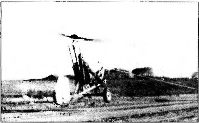
After tuning the engine and check the alignment of the gyro you can start taxiing on the ground and test flights.
 
RECOMMENDATION: develop skills to control gyroplane on the ground and in the air
 
Start the engine and warm it. Left hand spin the rotor blades of the propeller and increasing grip throttle speed pusher propeller, go for a run.
 
Low speed and observe the direction of movement with the front driven wheel, and when it comes off the ground — with an air rudder. Adjusting the position of the axle of the main air screw handle control of the gyroplane, achieve this state of equilibrium in motion, when neither the front nor the tail wheel does not touch the ground.
 
All turns and perform smoothly with a large radius. If you feel that the gyro is starting to get off the ground, and immediately relieve “gas”. Practice for half an hour. Only then you will be equipped with management skills.
 
Then you can move on to the test flights. Increase the frequency of rotation of the crankshaft of the engine and, once started, remove the gyro from the flight Posadas-strips. But immediately reset the “gas” and put in the car. Make sure that first touched the ground the tail wheel! All this should be done only against the wind.
 
Again increase the thrust pusher propeller, and repeat all its previous actions. Note the speed at which occur the take-off and landing—in the future it will need.
 
Having mastered these “jumps”, start real flights. At first, selecting a suitable location, fly straight, and then begin to master the bends. Keep in mind that the rudder is ineffective at altitude. Therefore, in the air turn, moving the axis of the rotor in the required direction. To maintain a constant height when cornering increase the thrust of the pusher propeller.
 
It may be that the rod is insufficient, especially for take-off. In this case, try to get off the ground in tow behind the car. After dialing the desired height, release the tow rope and continue your flight on your own. Of course, you will have to continue to boost engine since the greatest power is required for takeoff.
 
And some important tips. Before the flight the gyroplane walk around and make sure of reliability of fastening of all its parts. Check the fuel tank and record the fluid filler plug.
 
Don’t forget to wear a motorcycle helmet and goggles.
 
Finally, never fly over populated areas. And the air always inspect and analyze the surroundings for the event of a forced landing.
 
Have a good flight and maximum enjoyment from them!
R. MERKULOV, air force Colonel, retired, Professor


Recommend to read

  • GREENHOUSE-INDIVIDUALGREENHOUSE-INDIVIDUAL
    Seedlings of cucumbers and tomatoes planted in the middle lane, usually in an indoor soil — in greenhouses or hothouses. Unfortunately, the main material is plastic film, and the more...
  • ON TRACK BUGGYON TRACK BUGGY
    Motorsport fans have long been familiar with the term "rally". He is known and automodellista-skorostyam is one of the competitions cord racing models, in which miniature cars shall...