
I offer readers of our favorite magazine an automatic plant watering and spraying system of my own design, which has proven itself both indoors and in a greenhouse, winter garden, and flower bed. It consists of two interconnected subsystems: “sensor — water supply” (fig. 1) and an electronic control unit (fig. 2). While the first can be assembled even by beginners, the second is better entrusted to those with sufficient experience and knowledge in electrical and radio engineering. Originally intended to serve three (author’s prized) plants, the system can also be used as a multi-channel one. All channels are absolutely identical, which greatly simplifies installation.
The system’s operating algorithm is such that for most of the time the automation (except for the standby photorelay) and sensors are de-energized. This is done to improve equipment economy, avoid stressing plants with current constantly flowing through the soil, and prevent so-called electrochemical polarization, which leads to false triggering of the automation.
At the start of daylight, the standby photorelay trips, switching on the power supply and applying 12 V to the pump motor for 5—7 minutes (the interval set by the main timer). The motor begins filling the “hydraulics” with water and spraying the plants, dumping excess water through nozzles that act as relief valves in this case.
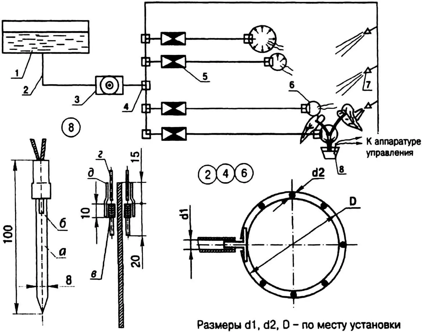
1 — water tank; 2 — flexible hose (silicone or rubber tube); 3 — electrically controlled pump; 4 — tee; 5 — water solenoid valve; 6 — drip irrigation ring; 7 — nozzle (sprayer from an aerosol can); 8 — homemade humidity sensor; parts 3…5 — from a VAZ-2109 windshield washer; number of parts 2,4…8 — as required;
a — double-sided copper-clad fiberglass; b — electrode (graphite pencil rod, 2 pcs.); c — contact wire winding; d — lead (MGShV wire, 2 pcs.); e — protective cover (compound or a piece of vinyl tubing)
The same 12 V is applied through its own time relay with up to a 15-second delay to the measurement sub-block responsible for clear and correct soil moisture measurement. If the moisture is below the level set individually for each plant, a high-level signal appears at the circuit output and is fed to the trigger input of the control sub-block. When it trips, it opens the solenoid valve for a duration set by another time relay, whose delay depends on the watering intensity, size of the growing container, and other factors.
After the set time interval elapses, the valve closes and water supply stops. The main timer automatically switches off the power supply, de-energizing both subsystems except the photorelay, which remains in standby until the next morning. If soil moisture is normal on the next startup, no watering will occur. The system will limit its supervision of the plants to the mandatory morning spraying — when the photorelay trips at dawn.
Now about the features of the “sensor — water supply” subsystem.
The humidity sensor is a probe made from a strip of fiberglass laminate from which most of the copper foil has been removed (only about 10 mm is left on top). Two pieces of graphite pencil rod (15—20 mm long each) are tightly wrapped with wire for 10 mm and soldered to the foil on opposite sides of the strip. Wires are soldered to the leads on top, and the whole assembly is sealed with compound.
The watering setup uses solenoid valves, flexible transparent tubes, plastic tees, and the windshield washer motor from a VAZ-2109 (the washer tank is small, so a 25-liter plastic canister is better). In the motor, brush pressure is reduced to lower noise and current draw.
A watering ring is formed from the tube around the plant, with small holes punched along its inner side. For row planting, the tube need not be ring-shaped; it can be run between rows. Spray nozzles are taken from aerosol cans. These parts are mounted above the flowers on a U-shaped bar and connected in series.
Sometimes with low or sparse foliage, spraying can affect the probe readings. In that case it should be covered with a conical cap that must not touch the soil. If the device is used over a large area, several probes in different locations can be connected to one measurement block.
Now about the operation of the principal electrical schematic. When sensor VR1 is darkened, its resistance increases, turning off transistor VT1. Transistors VT1—VT2 form a Schmitt trigger to provide hysteresis for slow input changes and ensure clean relay K1 operation.
When voltage appears on the gate of VT3, relay K1 closes the load circuit — the 12 V power sub-block. To keep it on for a limited time (5—7 min), transistor VT4 with the R8C1 discharge circuit is provided. As soon as capacitor C1 discharges below the threshold, VT4 turns on, shorting the gate of VT3 to common, and relay K1 drops out. The circuit stays in this state until the next evening.
During the day, capacitor C1 discharges through resistors R6 and R8. Thus, when the sensor is illuminated again, the relay will operate within the time interval set by R8 and C1.
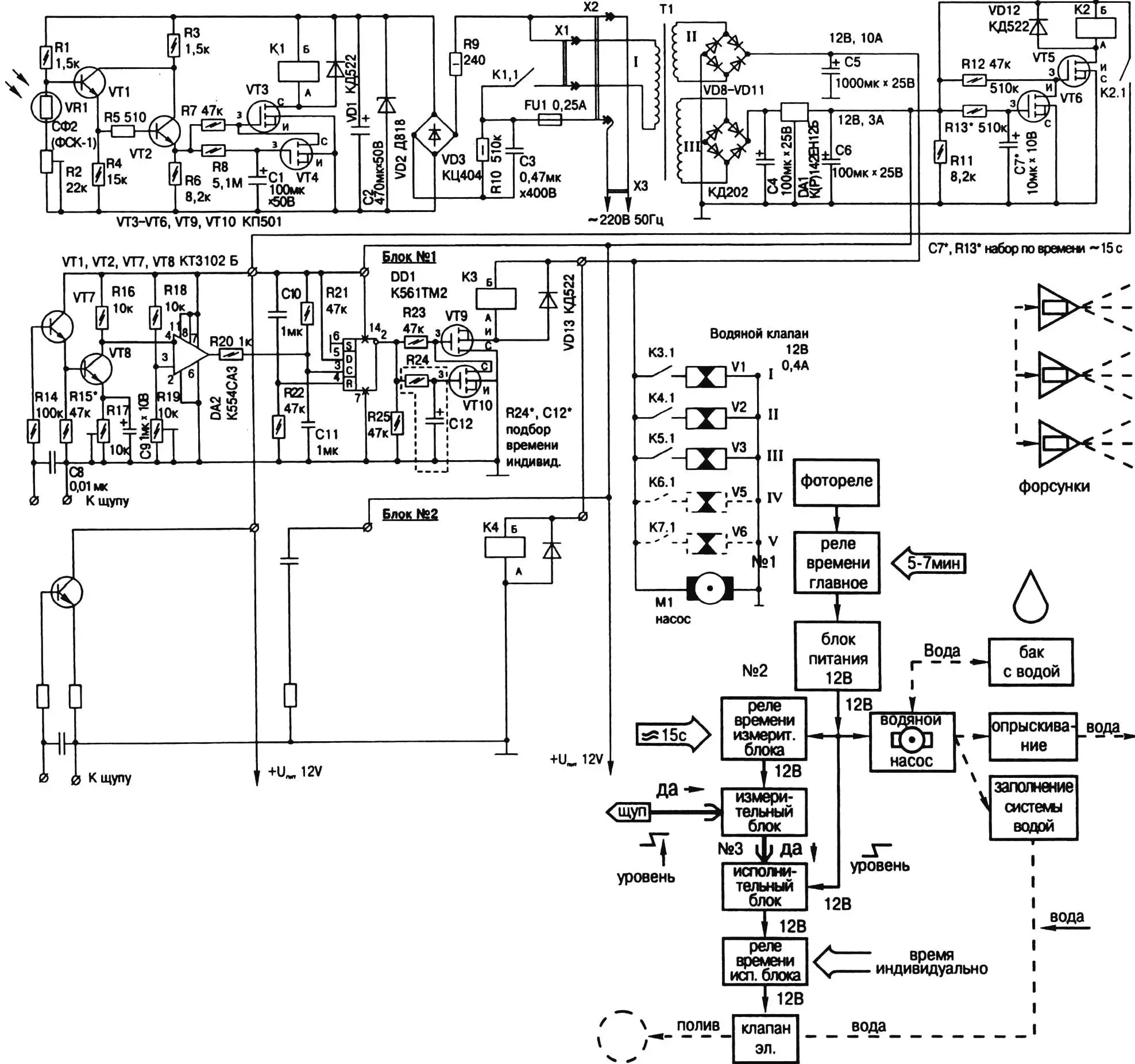
The device is powered from the mains using a transformerless circuit to reduce energy use. In standby it draws on the order of 30 milliamperes.
The 12 V power sub-block also has a time limiter on the output, similar to the photorelay. But the limiting time is different — 15 seconds, set by the R14C7 network.
The measurement circuit is built on a comparator; the trip threshold is set by trimmer R19. Paper washers under the knobs of R17 and R19 act as graduated scales.
The wiper of trimmer R19 is set to the middle. The probe is placed in soil at the desired moisture. Knob R17 is adjusted to find the point at which relay K3 trips. Adjustment is done separately for each plant (each channel).
The trigger on IC DD1 ensures clean relay K3 operation. To limit how long it stays energized (and thus watering duration), a limiter is added; its time is set by resistor R24 and capacitor C12. For easier debugging when swapping plants, these circuit elements are made as a removable module. It is useful to keep several modules tuned for different times (from a few seconds to a few minutes).
Practically all component information is in the principal schematic. It can only be added that fixed resistors are MLT type and trimmers are SP-3-19, and R17 and R19 can be replaced with fixed resistors after measuring different soil moisture levels. Capacitors C1, C2, C4—C12 are common K50-35 types, and C3 is K73-17 rated 500 V. Any relays will do as long as their coil is rated for 12 V and contacts reliably switch 0.6 A.
The transformer is ready-made or homemade, with two secondary windings capable of delivering 12 V at 1 A (stabilized for electronics) and 8 A (ordinary, for solenoid valves and pump motor). The ratings include some margin for expanding the device and adding new valves at 0.4 A per valve.
«Modelist-Konstruktor» No. 5’2002, S. SAVLYUKOV
Recommend to read
 A COMPACT CAR FOR THE BIG CITY
Ask car enthusiasts about which meaning is embedded in "tree" — the emblem of the famous French firm Citroen and you will get a variety of answers. And, maybe one out of ten say that the... THE PACK, NOT THE BASKET
Usually writing or computer table is a basket for unwanted papers and other debris. And how without it? In my opinion, much easier and more practical to have on hand for these purposes,...
