Designing internal stairs — for example, attic stairs — is often troublesome. For comfortable, large flights there is usually not enough room, and they end up very steep, which is quite dangerous, especially for older people.
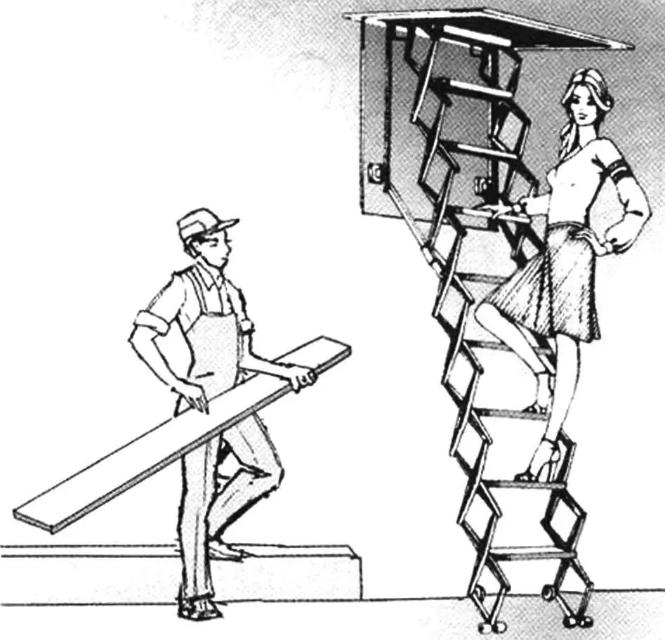
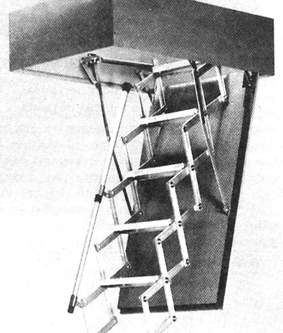
In one issue of an old Czechoslovak magazine, an interesting compromise design was proposed, which we offer to our readers. In the lowered position, this structure resembles an ordinary ladder with steps that are fairly easy to climb. When folded, it lifts up and does not take much space, fitting on a horizontal “door” leading to the attic. An electric motor, switched on from below with a button, drives the whole assembly.
The “door” in the ceiling
We deliberately omit some construction details, as they will in any case be done on site. Therefore anyone who takes on this idea should have a certain level of technical skill, while the drawing shown (Fig. 1) gives the necessary overall picture of the structure and its main units.
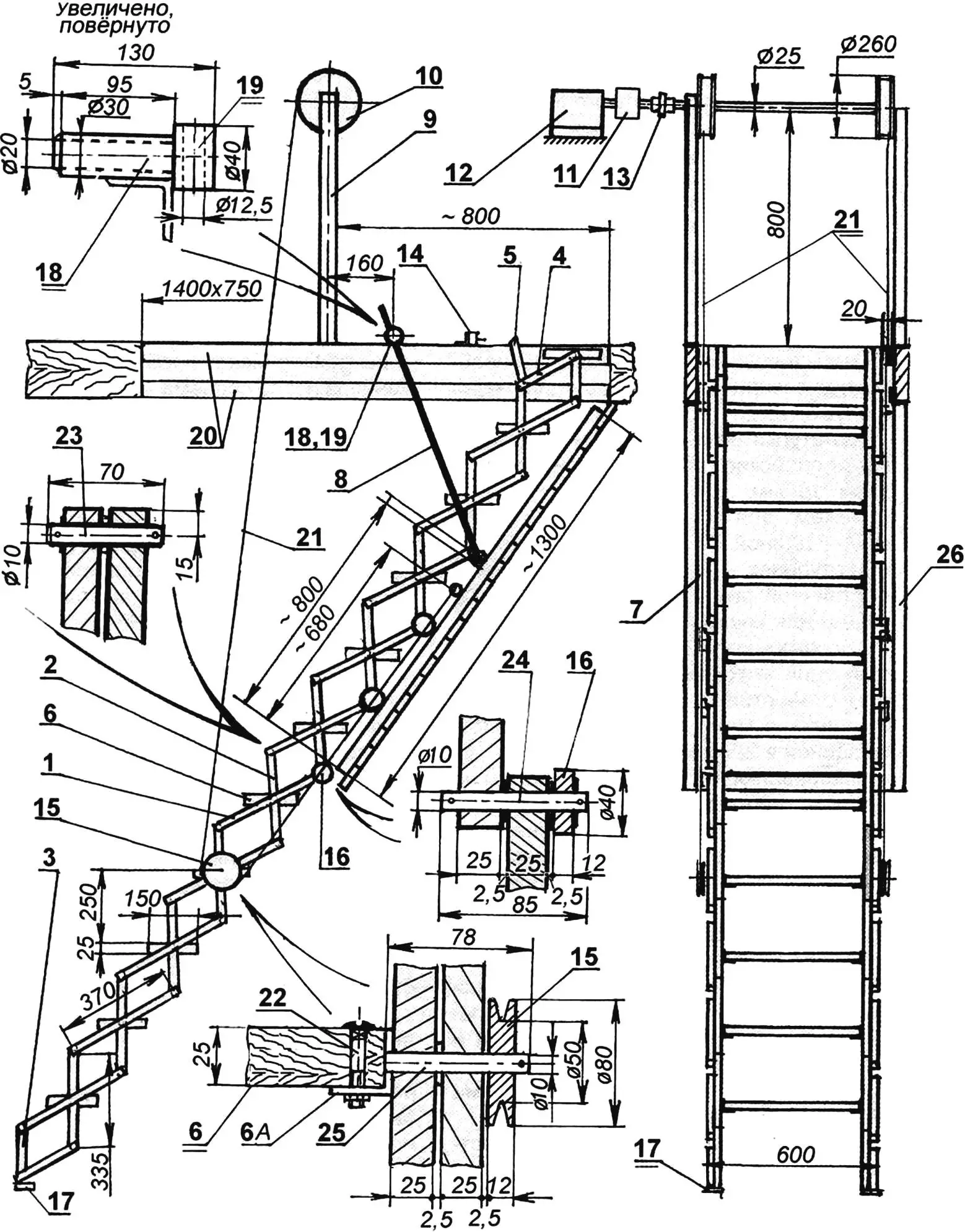
1 — long lever of the folding stair frame (outer, tube 25x25x2); 2 — short frame lever (inner, tube 25x25x2); 3,4 — shortened (end) levers of the stair frame; 5 — lever of the electric motor limit switch; 6 — tread (6A — its support); 7 — tubular “rails” for the stair frame rollers (2 pcs.); 8 — limiting tube (2 pcs.); 9 — drive drum upright (2 pcs.); 10 — drive drum (2 pcs.); 11 — worm gear; 12 — electric motor; 13 — drive coupling; 14 — limit switch; 15 — stair pulley; 16 — stair roller; 17 — lower limit switch; 18 — journal pin; 19 — cylinder (or bearing); 20 — hatch recess framing (frames of steel angles); 21 — cable (rope); 22 — bolt for fastening a stair tread; 23 — axis of stair levers; 24 — axis of stair rollers; 25 — pulley axis; 26 — frame of the “door” panel
An attic hatch is usually already present in an attic building. Therefore, for stairs 600 mm wide, you will need to make framing measuring 1400×750 mm. Its rim must be reinforced properly. For this, use steel angles 50x50x3 mm, from which two identical frames (20) are welded: one is fixed on the hatch from above, the other from below, and then the frames are welded together or screwed to the hatch rims.
The frame of the “door” panel (26) is also made of angles, but smaller ones may be used, 36x36x3 mm, and the “door” size with angles is chosen so that it fits into the hatch frame with a clearance (around the perimeter) of at least one centimeter. Later, at the finishing stage, boards or strips can be inserted into the “door” frame instead of a solid panel, but already now two tubes (7), 70x35x2.5 mm, must be attached to the frame — these are the “rails” along the long sides of the “door”, (10 mm from its surface). The “door” should swing on three (100×100 mm) door hinges, one half of which should be screwed to the narrow rim of the hatch.
Stairs
The main material for the stair elements is closed-profile steel tube 25x25x2 mm. The tube must be cut into separate levers of two sizes: “horizontal” pieces (1) will be about 400 mm long, and “vertical” ones (2) — about 365 mm. (The number of pieces depends on the distance between floor and ceiling. For example, at a height of 3.5 m it is enough to prepare 20 pieces of each). At the bottom and top ends of the stairs, four shortened pieces (3, 4) are attached, about 200 mm and 182 mm long.
In each lever in the middle section of the stairs, drill three holes 13 mm in diameter: two at the edges and one in the centre. Washers with inner diameter 13 mm and thickness 1.5 mm should be welded to these holes. Their ends should be welded shut, but these steps can be skipped.
Metal rods (axles) 10 mm in diameter are inserted into bushings (or holes); they are cut to length in advance: for joining a pair of levers — 70 mm (23), for tread attachment — 78 mm, for joining the stair frame — 85 mm (24) and, finally, for attaching levers at the “cable” rollers — 78 mm (25). To fix these axles, drill 3 mm holes at their ends for cotter pins, and place 2.5 mm thick washers between the levers.
Guide wheels (16) are mounted at the fourth, fifth and sixth joints. They can be made of hard plastic, or ready-made wheels can be used, for example from a baby stroller. Tubes (25) that will hold the treads (6) are welded to short levers or angles (6A), so that when the stairs are lowered the steps are horizontal. In addition, 6 mm holes must be drilled in these angles (6A) and treads; the treads themselves are bolted on with bolts (22).
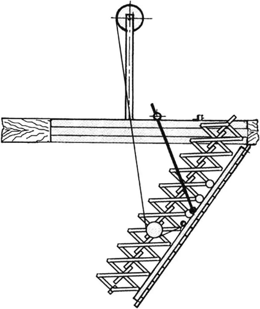
A guide pulley (15) for the lifting cable (21) is attached at one of the stair lever joints. For other dimensions the pulley position will change. It must be such that when the cable is tensioned the stairs fold first, and only after they are fully folded does the “door” itself rise.
Two guide (or limiting) tubes (8), about 900 mm long and 12 mm in diameter, must also be installed for the stairs. The lower end of these tubes is attached to one of the lever joints, while the upper end of the other has a leading roller; M12 thread must be cut for it and a journal (18) with a 12.5 mm hole screwed on. A rotating cylinder (19) or bearing, which will run along the hatch rim, is fitted onto this journal, made as an axle. The journal must be fixed on the tube so that when opening, the stairs have an inclination of up to 50°.
Drive
At this point the work is, in principle, finished — the stairs can already be used. However, extending and lifting the stairs by hand will be rather awkward, so it makes sense to add an electric drive.
The winch drive system for lifting the stairs is quite complex. It uses an electric motor (12) rated 0.8 kW. The motor shaft drives a worm gear (11) with a coupling (13), which provides the necessary braking when lowering the stairs and, after lifting, holds them in the upper closed position. Knowing the worm gear ratio, the winding drum sizes must be chosen so that the cables move at a speed of at most 5–6 metres per minute. The motor is mounted on a special frame or attic cross-members. The winding drums (10) and their uprights (9) must be arranged so that you can walk underneath them after climbing the stairs. The drums are mounted on bearings on the shaft.
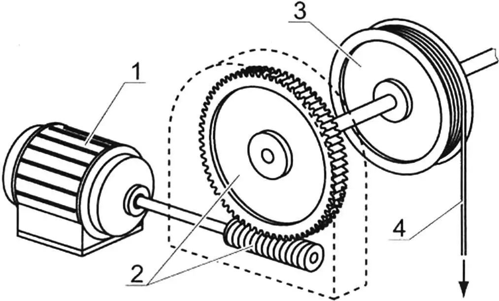
1 — motor; 2 — worm gear; 3 — drum; 4 — rope (cable)
The electrical circuit must protect the motor, reverse rotation direction, and automatically switch it off at the end positions. A 25 amp fuse and a 16 amp three-pole switch perform the first task. For reversing, electromagnetic switches are used that change phase and thus direction.
Limit switch 14 on the hatch frame is actuated by lever 5. The second limit switch (17) must be placed on the stair leg so that it trips when the stairs are fully lowered.
When working with electricity, do not forget safety precautions; preferably, have a qualified person make all connections.
“Modelist-Konstruktor” No. 10’2010
Recommend to read
 Sandwich chimneys: design and benefits
One of the essential elements of the furnace chimney. With its help output products of combustion. Such an element can be of different types. Now widespread sandwich chimneys, which are... A SOLDERING IRON WITH A SYRINGE.
Anyone, even a well-equipped modern machine shop to do probably without soldering. And no matter how they fought for the engineering is still in front of us (according to the definition...
