
 Laboratory and technical creativity SGPTU № 33 at the Leningrad Association “Svetlana” is already known to our readers. Dozens of original designs, has earned diplomas at many exhibitions, inventors ‘ certificates, rationalization proposals introduced, giving a substantial economic effect, the laureate of the medal is the result of the work of LTT for several years of its existence.
A recent publication (see “M-K” № 11 in 1977), which mentioned an interesting development LTT — planetary gearbox is a curious design, caused a lively reader’s interest. The editorial Board received dozens of letters with requests to provide additional information about the unusual mechanism. Carrying out the wishes of readers, we were invited to perform in the journal of the head of the LTT Alexander Mikhailovich Ivanov.
Our “planetary” can be used in such units, where other gearboxes or gear boxes with the same transmitted power may not be used at all: for example, in downhole motors of the electro-drills, where the diameter of the gear is limited to standard pipe. Axle gears in our gear box unlike the other, are not parallel, but are angled to each other. This seemingly insignificant difference and given the opportunity to create a mechanism with extremely small dimensions.
All planetary series (level of deceleration) “planetary” is formed of the same parts, which ensures good manufacturability of its manufacture. It is no coaxial tubular shafts, and to enable any release requires operation of only one brake element. The number of gears in a box like this can be almost any. We, in particular, made it in a car, a four-speed variant (Fig. 1).
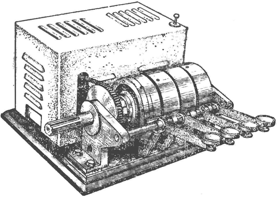
Fig. 1. Appearance planetary gearbox (model).
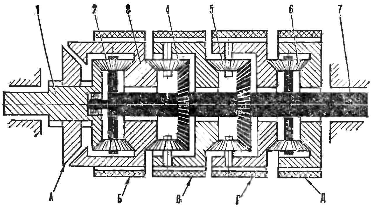
Fig. 2. Kinematic diagram of the gearbox:
1 — output shaft 2 satellites, the third gear, 3 — a block of two Central gears, sitting freely on the main shaft, 4 satellites the second transmission, 5 — satellites the first transmission, 6 — satellites into reverse, 7 — output shaft;
A frictional conical clutch fourth (direct) transmission, B is the band brake third gear, In the band brake second gear, G — band brake the first transmission, D — band brake reverse
The kinematic diagram of the mechanism depicted in figure 2. As you can see, the box provides four forward speed and one rear. Fourth gear is direct, that is, the drive shaft will then be locked with the driven bevel friction clutch. The reverse can be enabled by activating the band brake D, and three drive — brakes G, and B by using the hydraulic system.
Schematic diagram of the hydraulic drive — on figure 3. With it, any transfer included only one rotary valve.
The hydraulic system provides gear shifting (since the second) without breaking the power flow, i.e. with some overlap. The presence of accumulator allows to carry out quick, but at the same time, the smooth integration of each new transmission. The hydraulic drive gives you the opportunity to overrun from any gear. And each can be enabled, bypassing the intermediate. This is useful, for example, when braking of the machine motor.
Transmission of LTT is so versatile that it can even provide a tool such as electricity or newmodel, which significantly expands the range of applications. For example, it becomes possible to drill to thread, turn bolts or nuts. Another convenience is that the required transfer of such drills will be activated without stopping the engine by blocking one of the three brake drum band brake. Lock drum is smooth, and feels it working by changing the position of the brake arm. This helps protect the drill from damage.
The torque is transmitted to the driven shaft through the satellites, thus the bearings are unloaded from the action of radial forces. The number of planetary satellites in each row must be at least two. Good results are obtained with the use of plastic wheels with the use of gearing Novikov. As the transformation of the torque in our transmission is automatically increased contact area, perceiving this moment on the driven shaft. For example, in third gear (when stopped, the driver 4) this moment perceives only one gear is rigidly connected with the driven shaft, the second has two wheels, and for the first three.
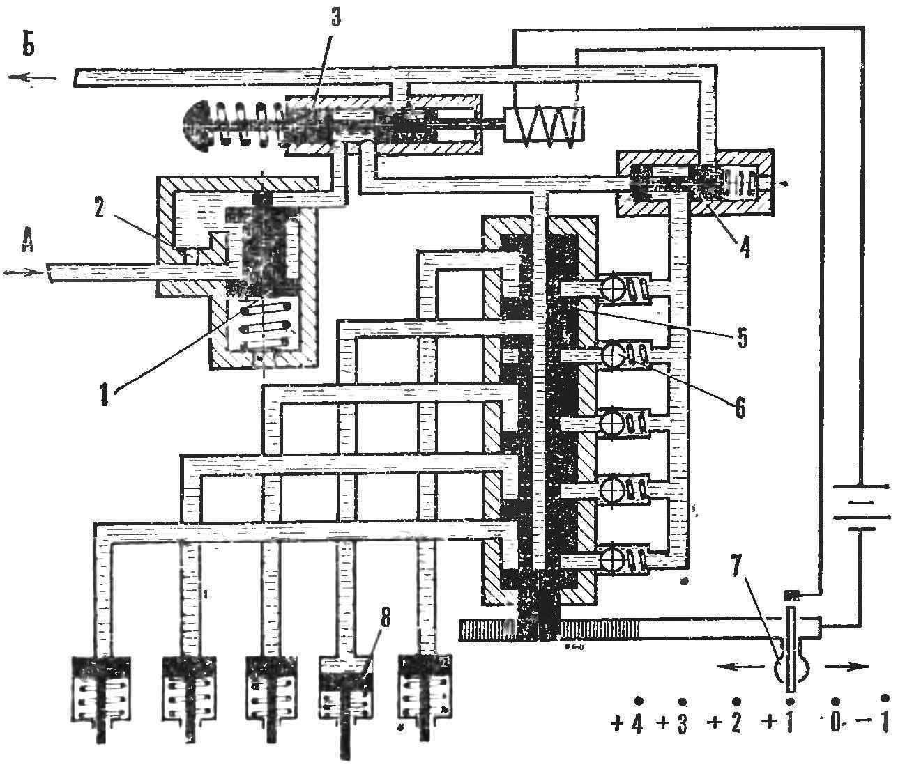
Fig. 3. Diagram of hydraulic transmission:
1 — the accumulator, 2 — grooved hole, 3 — drain valve, 4th valve overlap transmission, 5 — control valve of the rotary type 6 — return valves on the discharge channels 7 — lever control of the rotary valve, 8 — cylinders pereklyucheniya transmission;
A — the tubing from the pump line, B-the pipe from the drain lines.
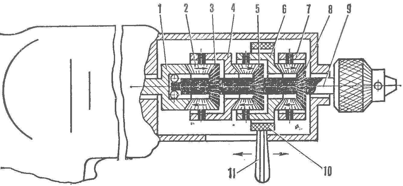
Fig. 4. Drill with planetary gearbox:
1 — the Central wheel, rigidly connected to the motor shaft, 2 satellites, 3 — center wheel third gear, 4 — carrier third gear, connected to the Central drive wheel of the second stage, 5 — center wheel second gear rigidly connected with the driven shaft, 6 — carrier of the second transmission mated to the Central drive wheel of the first stage, 7 — drove to the first transmission, 8 — the Central wheel first gear rigidly connected with the driven shaft 9 — driven shaft, 10 — band brake, 11 — the handle to lock the carrier band brake.
If necessary, the number of delay stages can be increased and even type reverse.
Ratio gear box increases by geometric progression, but may be adjusted due to the angle of intersection of the gears.
If you do not want to transfer large capacity, the transmission can be formed by a smooth conical wheels with a high coefficient of friction. This will only increase the number of satellites in each row, and the clutch of the clutch to provide a preload spring. To compensate for wear of the friction surfaces of the individual elements of the transmission should have a floating design.
A. IVANOV, Leningrad
Recommend to read
 RAPID HEATING OF THE WATER IN THE BATH
To produce hot water in the bath are often used bak-register on the tube of the furnace (or boiler in the furnace itself) and external tank in the sink. The circulation of water between... THE FLOORBOARD CREAKED
Eventually, the old plank floors are beginning to demand greater attention: that the weakened floorboards start to play under my feet and to communicate by squeaks, reminding of the...
