Maneuverable, compact vehicles are vital, especially in snowy and wooded areas. In some countries, for example the USA, Canada, Japan, this problem is solved by the production of small-sized machines such as motorarts. Our industry also began to produce such equipment: motorcycle guns such as “Buran”, “Amurets” and others appeared. However, these cars are more of a pleasure car; they do not even have an insulated cabin.
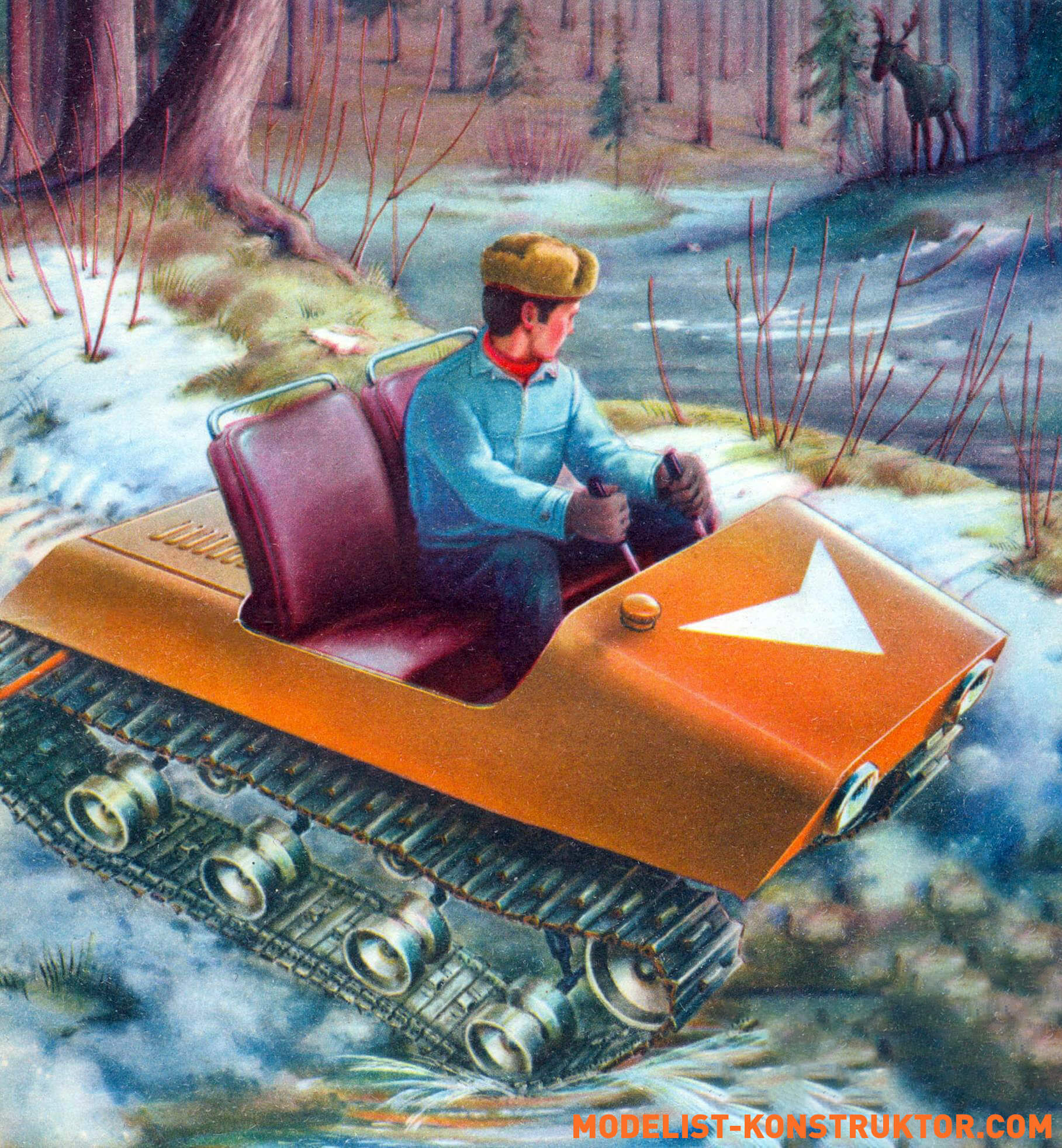
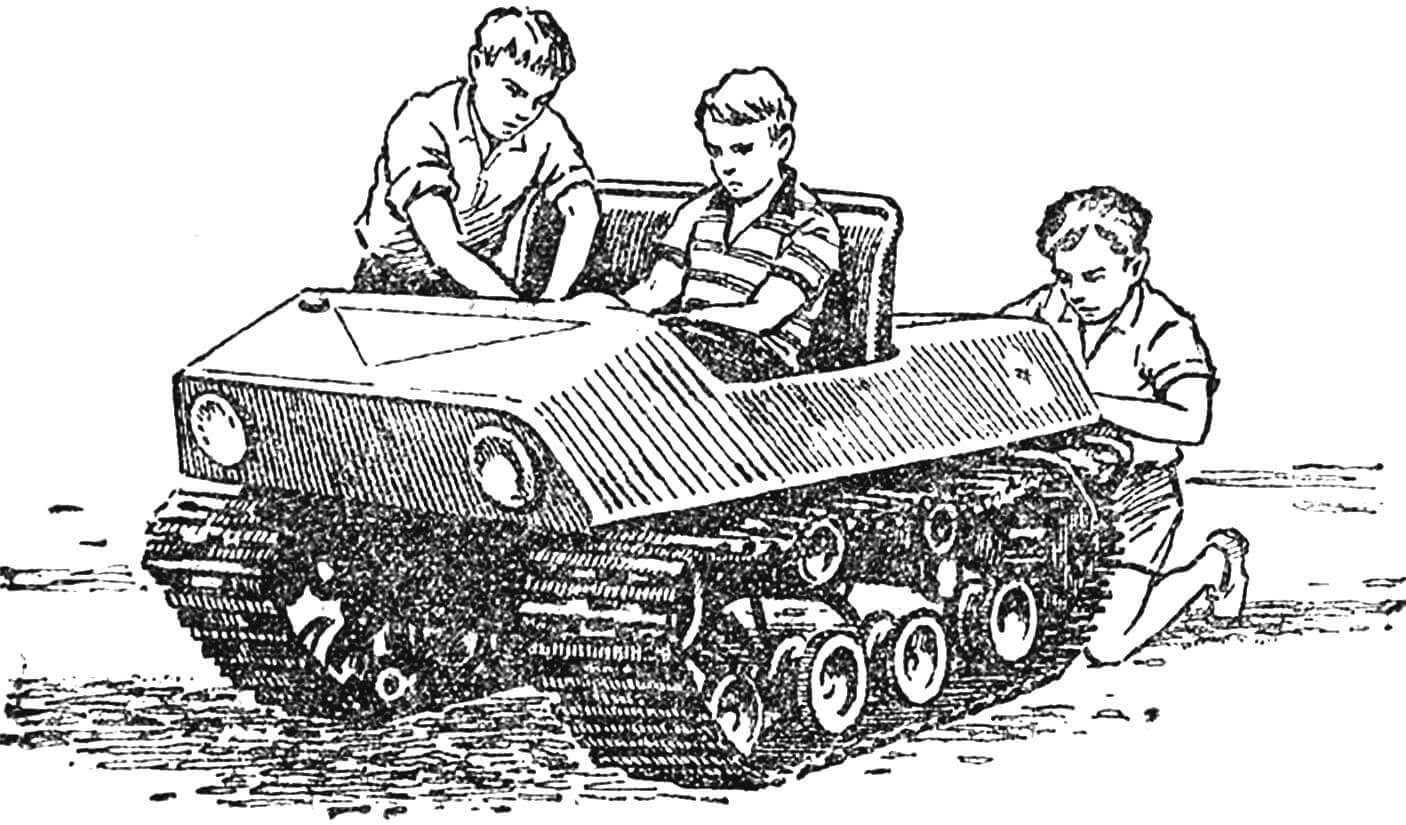
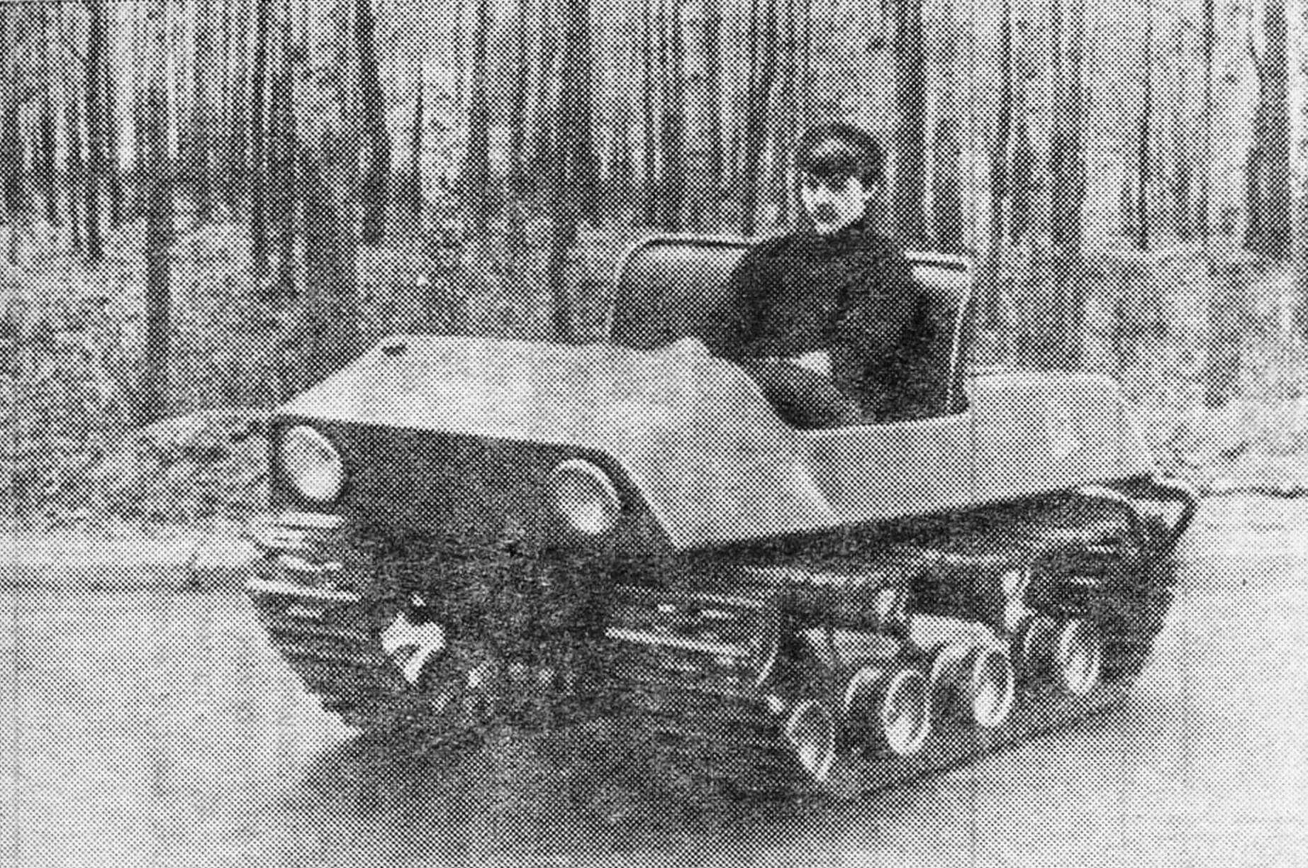
In our small-sized equipment design laboratory, we built a small but “working” machine – a micro-all-terrain vehicle for a forester (see photo). It combines the advantages of large tracked all-terrain vehicles: high cross-country ability and maneuverability, the ability to have an insulated cabin, the necessary power and speed of movement – with small dimensions and weight.
All this makes the all-terrain vehicle convenient for use by workers of the national economy in difficult areas of our country.
DESIGN DESCRIPTION
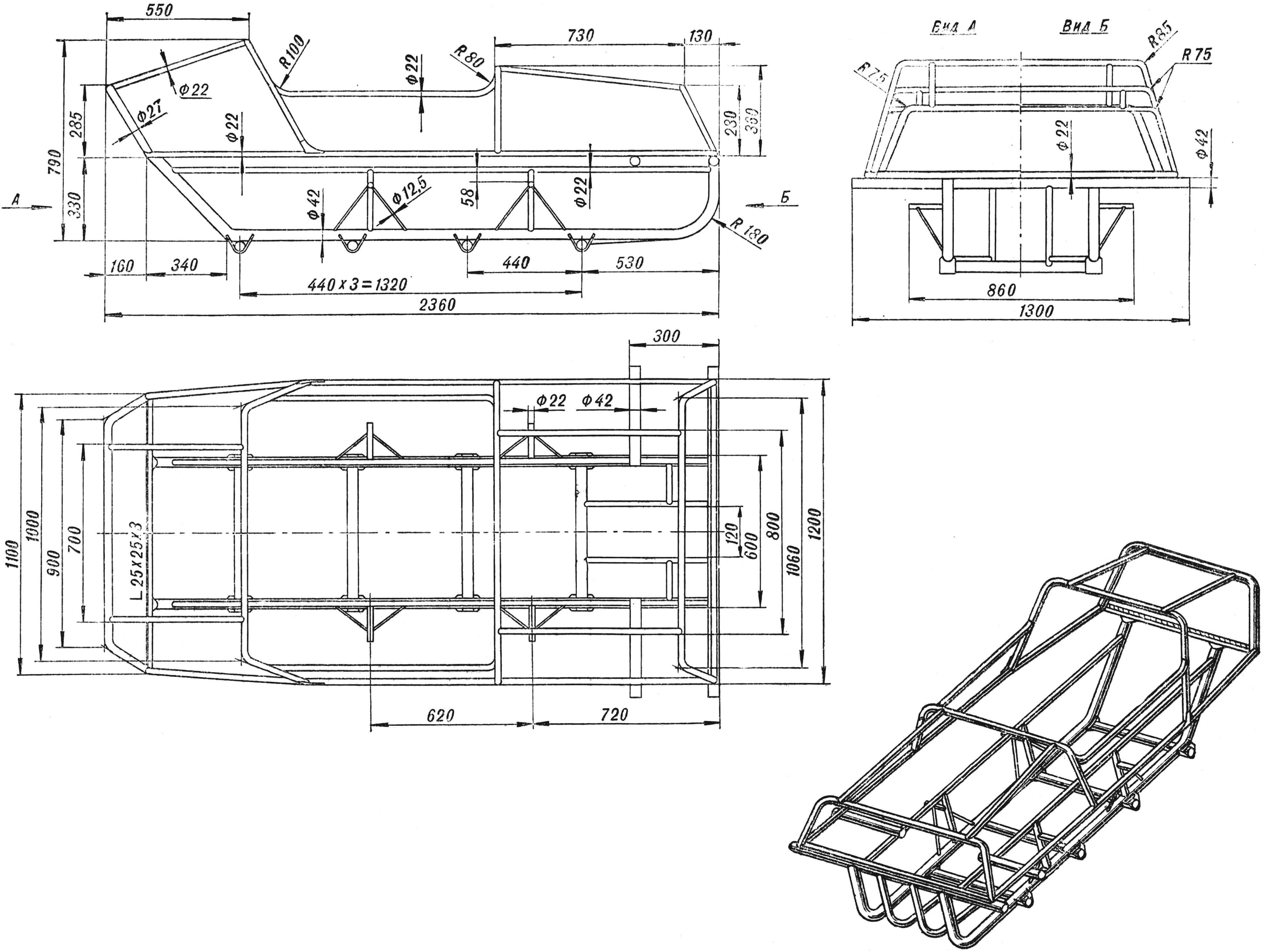
The frame (Fig. 2) is a closed rectangular shape, consists of two longitudinal spars Ø 42 mm, to which four torsion bar suspension housings from the front axle of the S3A motorized stroller and pipes Ø 22 and Ø 27 mm are welded from below, repeating the silhouette of the body
The body is made of sheet steel with a thickness of 0.5-0.8 mm. To make it simple and convenient to make, templates were first cut out of thin cardboard. Then blanks were made from them, which were fixed by electric or gas welding to the pipes of the body frame.
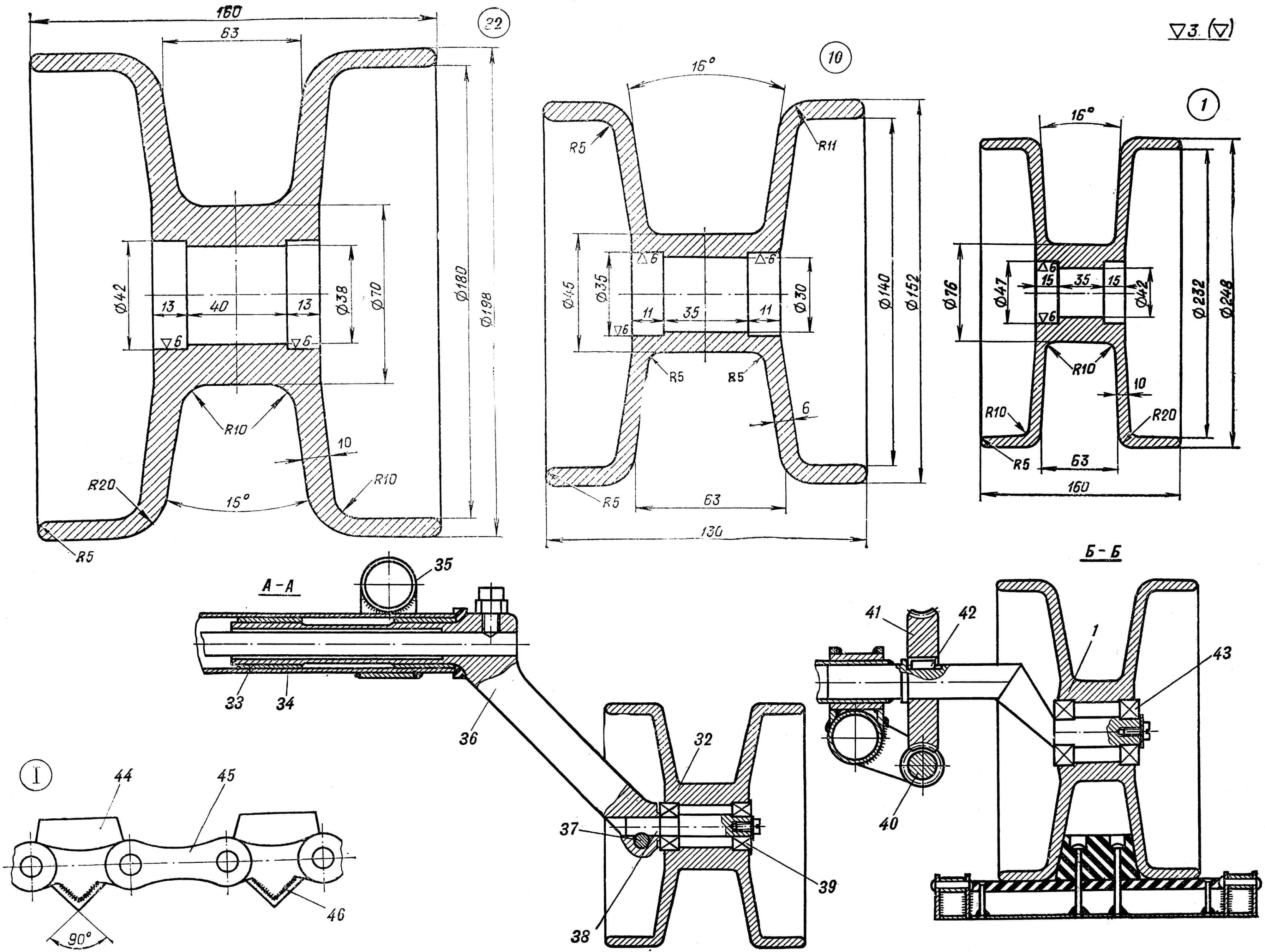
Mechanisms for tensioning the track are installed on the front of the frame (see Fig. 1, B – B).
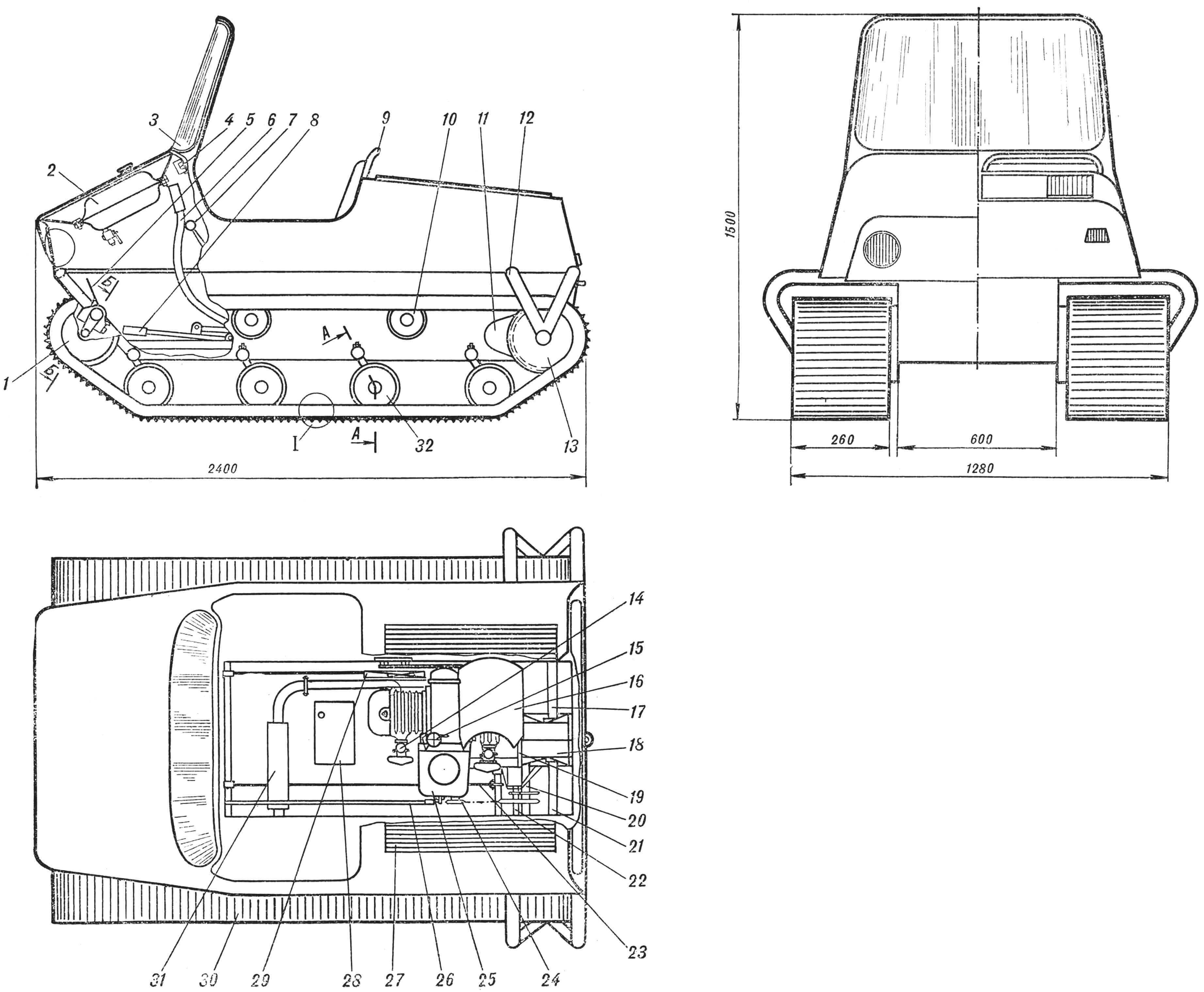
1 — tension roller, 2 — fuel tank, 3 — windshield, 4 — instrument panel, 5 — gas pedal, 6 — brake lever, 7 — gear shift knob, 8 — kick starter lever, 9 — seat, 10 — top support roller, 11 — band brake casing, 12 — axle shaft bracket, 13 — drive sprocket, 14 — carburetor, 15 — fuel pump, 16 — fan casing, 17 — axle shaft, 18 — differential, 19 — M-62 engine, 20 — driven shaft, 21 — axle shaft, 22 — intermediate shaft, 23 — brake rod, 24 — engine drive sprocket, 25 — gearbox, 26 — kick starter rod, 27 — blinds, 28 — battery, 29 — fan (casing removed) , 30 — caterpillar, 31 — muffler. 32 – support roller, 33 – bushing, 34 – torsion bar housing, 35 – frame, 36 – torsion bar lever, 37 – locking bolt, 38 – roller axle, 39 – bearing No. 302, 40 – worm for tensioning the track, 41 – worm wheel , 42 — key, 43 — bearing No. 303, 44 — tape guide, 45 — chain, 46 — lug.
The gas tank is located in the front part of the body under the hood. Fuel is supplied to the carburetors by gravity. Instrument panel from a UAZ-452 car. It has an ignition switch, a gasoline level indicator in the gas tank, an engine temperature indicator, and turn signal lights.
The windshield is made of organic glass and is secured in a tubular frame with rubber sealing.
In winter and in bad weather, a canvas cabin is installed, which is stretched over a removable frame made of duralumin pipes Ø 18 mm. The driver’s compartment is heated from a muffler, which is attached to the engine exhaust pipe using flanges. In winter, it is located under the driver’s feet, and in summer, thanks to a flange mount, it is turned in the opposite direction and placed under the right track. Additional heating is provided by warm air from forced engine cooling fans.
The engine is a modernized M-62 Ural. Located in the rear of the body. Converting it to forced air cooling is as follows: a shaft is brought out through the front engine cover (Fig. 3, item 13), which is electric welded to the small timing gear. Bearing housing No. 204, which is the second support of the fan drive unit, is welded to the front engine cover using argon-arc welding. In the absence of argon-arc welding, the bearing housing can be secured with M6 bolts through a gasket to avoid oil leakage from the engine crankcase. The fan drive shaft, together with the small timing gear, is secured to the engine crankshaft with a key and an M8 bolt.
A double-groove pulley is mounted on the drive shaft (Fig. 3, item 6), which, using V-belts, transmits rotation to two driven pulleys. Eight-blade axial fans are mounted on them. The pulleys are located directly in front of the engine cylinders and are mounted on brackets that are welded to the body frame.
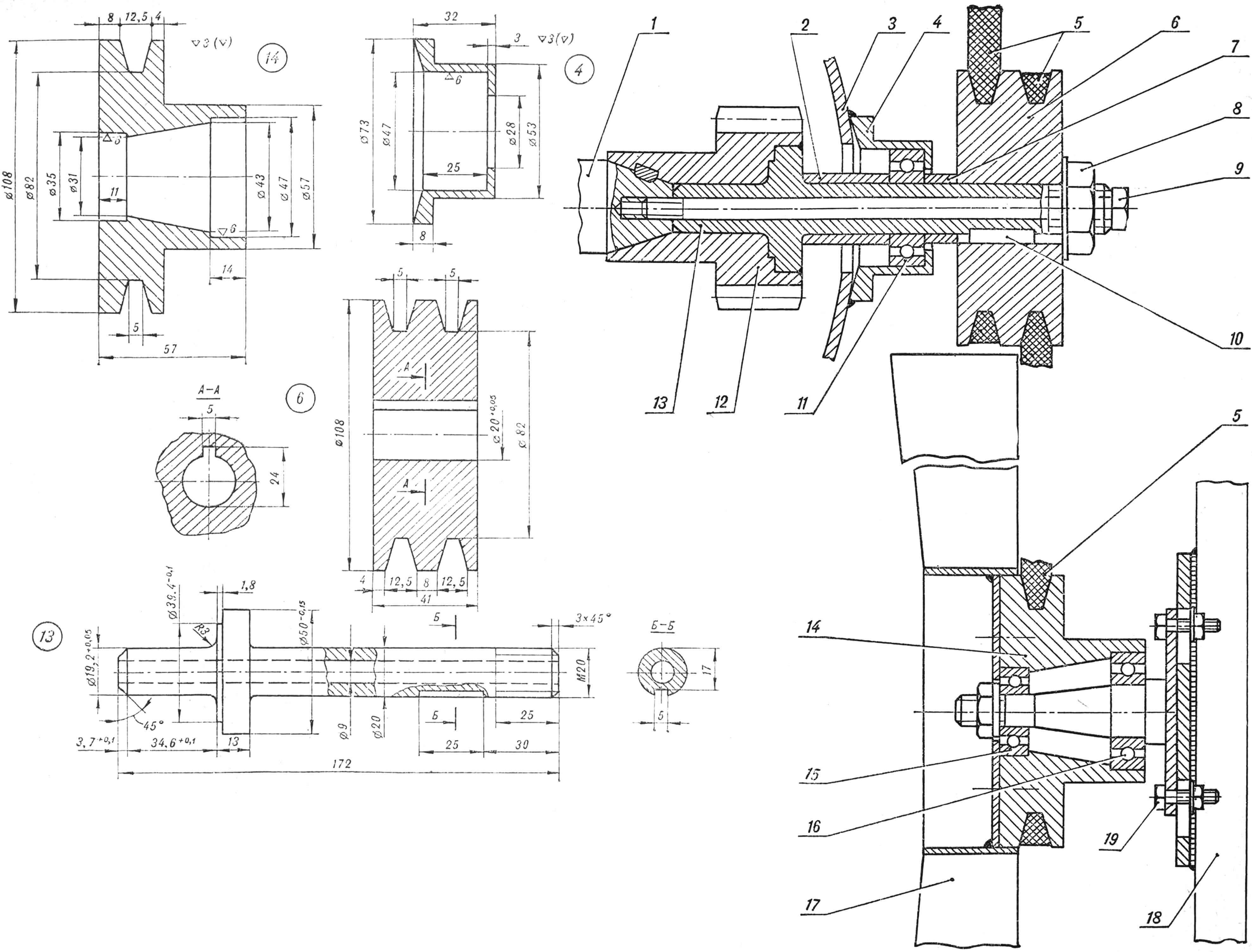
1 — engine crankshaft, 2 — spacer sleeve, 3 — front engine cover, 4 — bearing housing, 5 — V-belt, 6 — double-ribbed pulley, 7 — spacer sleeve, 8 — pulley mounting nut, 9 — M8 bolt, 10 — key , 11 — bearing No. 204, 12 — small timing gear, 13 — fan drive shaft, 14 — pulley, 15 — bearing No. 202, 16 — bearing No. 204, 17 — eight-blade fan. 18 – frame, 19 – M10 bolt.
The air flow is directed to the cylinders using casings (Fig. 1, item 16, another fan casing is not shown). After the cylinder has cooled, the air flow is vented out through the louvers of the bottom of the engine compartment, which are located in the direction of travel of the all-terrain vehicle. In winter, the underbody blinds are closed and air flows into the cabin. Air is taken in for engine cooling through louvers in the upper covers of the engine compartment.
The engine is started manually using a lever located on the left side of the driver’s seat. The lever is connected by a rod to a shortened kick-starter pedal.
The all-terrain vehicle uses a chain drive from the engine to the differential. This is caused by the structural location of the engine on the frame of the all-terrain vehicle and the use of a differential from a C3A motorized wheelchair, adapted to a chain drive.
Conversion of the M-62 “Ural” engine for a chain drive of the secondary shaft of the gearbox is as follows: the cardan fork is removed and the seat of the sprocket (from the Izh-56 motorcycle) is machined, having a pitch of 15.88 mm and the number of teeth – 18. The sprocket is welded to cardan fork by electric welding.
During testing of the all-terrain vehicle, it became clear that it was necessary to install a reduction intermediate chain gearbox with a gear ratio of 3. This made it possible to reduce the maximum speed to 50 km/h and increase the traction force on the tracks. Rotation from the gearbox to the differential is also transmitted using a chain drive. Thus, torque is transmitted from the engine to the gearbox and through the gearbox to the differential shaft (see, Fig. 4), then through the differential to the drive axle shafts. Two sprockets are attached to them, having a pitch of 37 mm and the number of teeth – 26 (Fig. 4, item 4, 23). The sprockets drive the tracks. Since the axle shaft protrudes significantly beyond the frame support and can bend under load, its outer end has additional support in the form of a bracket attached to the body frame.
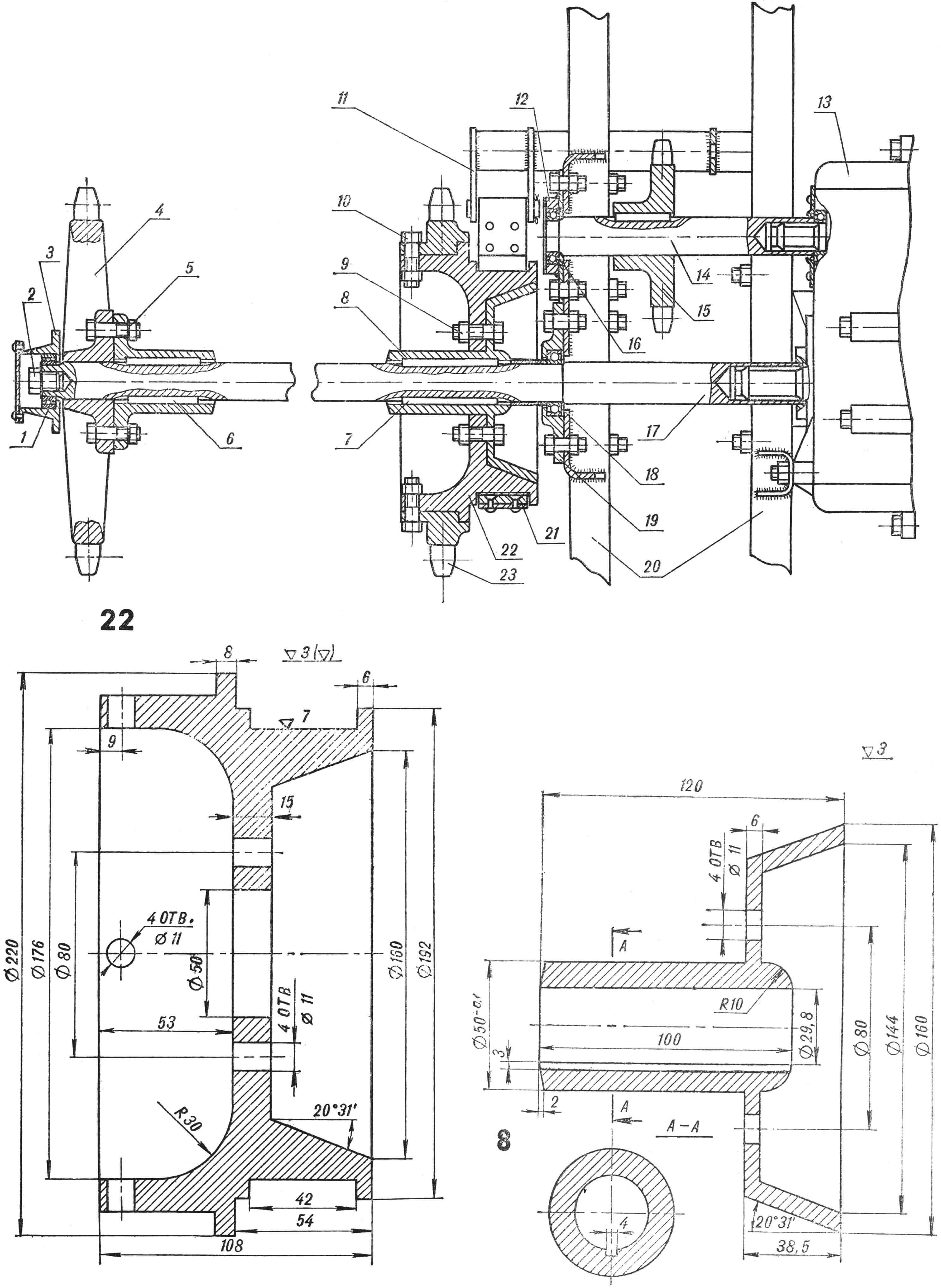
1 – bearing No. 205, 2 – M14 bolt, 3 – external axle support, 4 – drive sprocket, 5 – M10 bolt, 6, 7 – keys, 8 – brake pulley hub, 9, 10 – M10 bolts, 11 – band lever brakes, 12 — bearing housing, 13 — differential (C3A), 14 — differential shaft, 15 — differential shaft sprocket, 16 — bearing No. 205, 17 — axle shaft, 18 — bearing No. 206, 19 — bearing housing, 20 — frame, 21 – band brake, 22 – brake pulley, 23 – drive sprocket.
The all-terrain vehicle has four forward speeds and the same number in reverse. Switching gears, as well as reversing the all-terrain vehicle, is done with one lever taken from a UAZ-452 car.
The all-terrain vehicle turns by braking one of the two differential axles. When one caterpillar slows down, the other begins to rotate at double speed, as if running ahead: the all-terrain vehicle turns.
To brake the differential axle shafts, a band brake is used (Fig. 4, item 21), which consists of a brake pulley attached with M10 bolts to the hub sitting on the axle shaft, and a metal belt 38 mm wide. Friction linings measuring 40X70X6 mm are attached to it with copper or aluminum rivets. When operating, the band brake should cover approximately three-quarters of the brake pulley. One end of the band is attached to a bracket welded to the frame, the other is pivotally connected to the drive lever (Fig. 4, item 11) of the band brake. It is operated by levers located in the driver’s compartment. The all-terrain vehicle uses two foot control pedals: gas and clutch. There is no brake pedal, since it is enough to pull both levers, having previously depressed the clutch, and the tracks are braked and the all-terrain vehicle stops.
The tracks are rubber-metal, with two parallel chains, pitch 37 mm (see Fig. 5). For the tracks, chains from the conveyor of agricultural machinery are used. The protrusions on the chain are processed into the shape of lugs made from angle steel 20X20X3. A rubber cord from a 7 mm thick conveyor is attached to them with rivets Ø 6 mm.
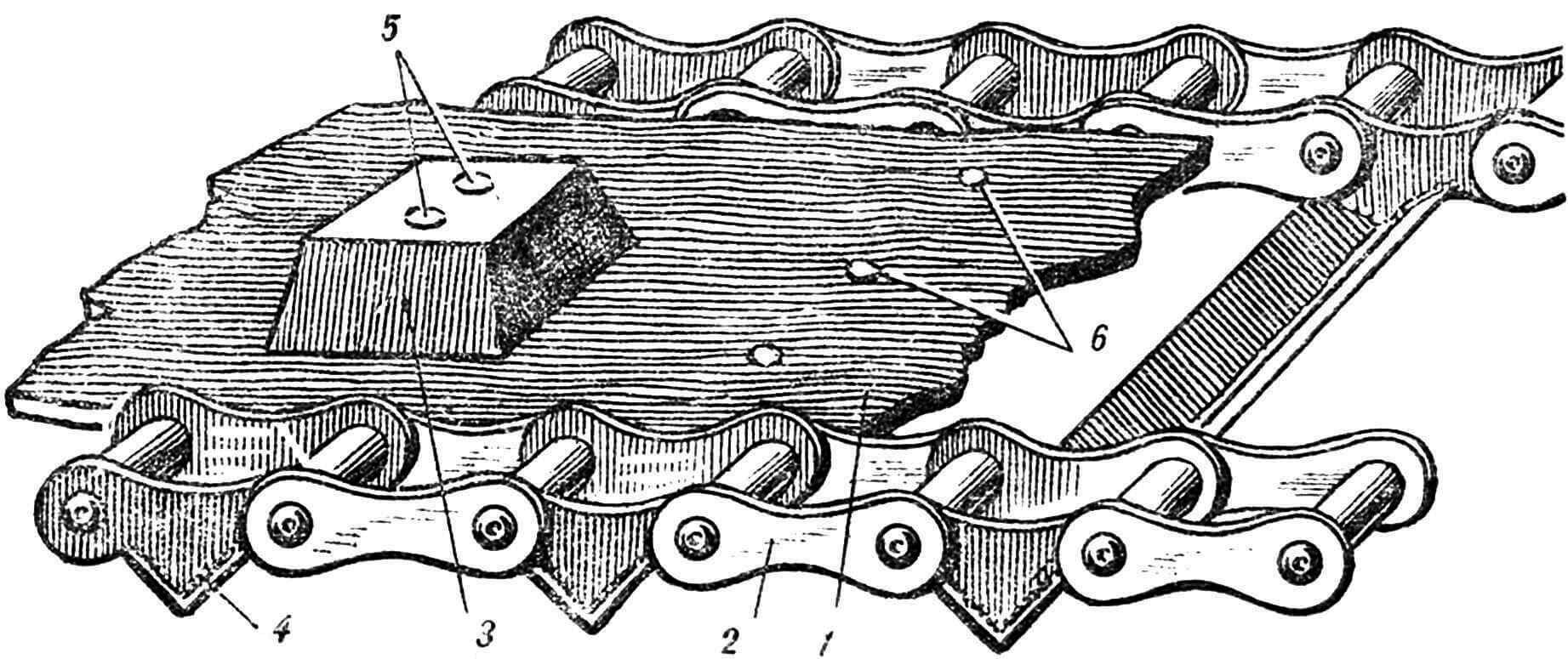
1 — conveyor mite, 2 — chain, 3 — belt guide, 4 — lug, 5, 6 — rivets.
To guide the movement of the rollers, rubber protrusions are used (Fig. 5, item 3) from a V-belt (profile “E” GOST 1284-57), which are attached to the belt with rivets Ø 8 mm, passing through the lug and welded to its outer side.
When designing a track, it is necessary to take into account that the middle of the thickness of the rubber band should lie exactly on the line connecting the centers of the chain rivets. Otherwise, the tape experiences deformation when working in tension or compression, which leads to premature wear.
Hardened chains, high-quality welding, and durable cord tape create a light and reliable track, and its sufficient width determines the specific ground pressure at full load within 70 g/cm 2 . The all-terrain vehicle goes well on loose snow, mud, dry soil and asphalt – almost silently, without the usual clanging of tracks.
A. NALIMOV, E. STEPANENKO, members of the club of young technicians of the Novosibirsk academic campus
THE ALL-TERRAIN VEHICLE IS BUILT BY BOYS
Three years ago, eighth-grader Zhenya Stepanenko came to our laboratory for the design of small-sized equipment at the KYUT Novosibirsk Academic Town. He brought with him a model of a crawler all-terrain vehicle that he had made at home. The thoroughness of the work, the proportionality of the parts of the all-terrain vehicle, and the creativity in the manufacture of parts evoked respect. It was felt that the young designer made his model with great love and diligence. The miniature all-terrain vehicle had two electric motors, powered by a flashlight battery, and could carry out several commands: move back and forth, turn in different directions, flash side lights. And Zhenya then said that all his life he had dreamed of building a real big all-terrain vehicle, and asked to be enrolled in the circle.
Work in the circle began with Zhenya keeping a thick notebook in which he wrote down his sketches: technical drawings, sketches of various cars, among which an airplane or a pistol suddenly appeared…
But one day, having finally come to a definite decision, Zhenya began making an all-terrain vehicle. Soon he brought a friend, Andrei Nalimov, into the circle, and the guys began to work together.
Not everything in the design of some parts became clear right away. For example, frame. The form emerged clearly. What about the pendant? Which one is better, more progressive? Where can I find out? In books, magazines. About the tank, for example, I read everything I could find in the scientific and technical library.
We settled on a torsion bar version, like on the T-34. We picked up ready-made pendants from the C3A motorized stroller. But is the rigidity of these torsion bars sufficient for the future all-terrain vehicle? I had to again call on special books for help, and first of all “Machine Parts”. We made a test calculation. He showed that the torsion bars from C3A are quite rigid. (Looking ahead, we note that the guys made a slight mistake: they only had to install additional spring shock absorbers on the front and rear torsion bars.)
Which engine should I get? Of course, I wanted something more powerful: an all-terrain vehicle. We decided to use an engine from the M-62 Ural motorcycle, since there were no others in the laboratory at that time. But there are many questions: how to place it on the frame so that it is convenient to service and repair in case of breakdown? How to transmit torque to the mover? What about cooling? It must be forced! And again books. The engine was studied thoroughly, disassembled and assembled with our own hands.
Some parts were used ready-made, but many had to be made ourselves. And the guys surprisingly quickly mastered the machines: sharpening, milling, drilling. At first, the manager grabbed the parts using electric welding, and then the guys, first out of curiosity, tried it, and then they learned to cook themselves.
Next is the mover. It is clear that only caterpillars. Where can I get them? There are no ready-made suitable ones. We came across a conveyor belt from some kind of agricultural machine. For the first time, we decided to use it, because it was not possible to make another one ourselves at that time.
…It was the second year of exciting searches and hard work. New nodes raised new questions. A caterpillar is not just a tape. We also need different rollers, drive sprockets, and somehow transmit torque from the engine to the tracks. Or final drives. We tried to adapt the clutch from the Izh engine – it turned out to be difficult and clearly unreliable. We decided to abandon final drives and use a differential from the same sidecar. They reasoned like this: if you brake one track while moving, the other, thanks to the differential, will move twice as fast, and the all-terrain vehicle will be able to maneuver. In addition, the differential from the C3A will allow the car to move in reverse. And again work: we need to sharpen the rollers. There are many of them, ten of them. Thanks to the bosses – they agreed to help, but demanded working drawings. I had to get serious about drawing.
And now two years of hard work is completed; The all-terrain vehicle has acquired its finished shape. But the very first tests showed a clear error in the gear ratio from the engine to the tracks: the all-terrain vehicle jerked faster than the motorcycle and stalled.
Driving in third and, especially, fourth gear was out of the question—everything needed to be redone.
Summer holidays have begun. And by the beginning of the new school year, the guys came with a ready-made solution: they need to install an intermediate reduction gearbox in the transmission and get serious about the tracks. Work on fine-tuning the car took another year.
And now the all-terrain vehicle is already being demonstrated at the regional competition “Young Technicians for Agriculture” and awarded a 1st degree diploma. A senior researcher at the Agricultural Institute, speaking at the rally, noted the great practical usefulness of such machines and expressed hope that over time the guys will “bring” it to a production model.
Zhenya was finishing school, and he had to decide where to go to study. Obviously, it was not by chance that he made this choice: Moscow Higher Technical School named after N. E. Bauman, Faculty of Mechanical Engineering, where there is a department dealing with tracked propulsion systems.
And Andrei moved to tenth grade. Now he brought an assistant with him, and work continued again. By this time, the project for the new caterpillar was ready: its manufacturing technology had been carefully thought out and materials had been selected. The caterpillars, made entirely by hand, were lightweight, silent, and durable. More trials, and the long-awaited joy of creativity – everything is in order!
Andrey is finishing tenth grade. There is no question about the future at all – of course, to Baumanskoye, to Zhenya!
What about the all-terrain vehicle? Show it at the next exhibitions? Or maybe expand its capabilities: for example, equip it with a bulldozer blade and hydraulics for control? But this is already the task of the next generation of young designers.
Of course, from an engineering point of view, the design of the all-terrain vehicle is far from perfect. But the guys’ approach to creating a car is important: great passion, hard work and perseverance in achieving their goal. All this ultimately helped them choose their future profession.
I am sure that after graduating from university, Zhenya and Andrey will become good engineers.
V. TAMBOVTSEV, head of the laboratory for the design of small-sized equipment, KYuT SB AN USSR, Novosibirsk
Recommend to read
 WITHOUT PEGS
Often at home you want to hang for drying items that cannot be secured with pin (for example, snails tiered photoback). Succeed with a string tied to nails or sticks out in any hole... SEEDER-DORADCA
On private land, perhaps only a decorative grass — raygrass — tracking, scattering the seeds. The vast majority of annual flowers and vegetables planted in rows: so the plants are easier...
