
 Since the invention of engineer D. Zimmerman of the GDR flat disk of the spool to control the inlet of the working mixture in two-stroke engines, slide valve gas distribution has found wide application in racing engines for many leading companies.
The use of the valve allows to the asymmetric phase of the inlet of the working mixture and the advantageous shape of the intake tract by shortening its length and increasing radius turn the flow of the working mixture. Under other equal conditions, it gives the opportunity to achieve greater filling ratio of the cylinder with fresh mixture, and hence more power.
Work on boosting the engine, providing the installation disk of the spool, of course, more complicated than the same operation with a piston gas distribution. But spool the engine is easier to choose the optimal phase of the beginning, end and duration of intake. This engine is easier to adjust for maximum power and throttle response.
The article describes a high-powered racing motor with spool distribution based on mass-produced domestic motorcycle engine “Sunrise” with a displacement of 175 cubic inches.
Speaking on the map with this engine, the author in 1973 and 1974, has repeatedly won prizes at the winter Championships of the USSR and RSFSR. The engine is created in the experimental laboratory of micro cars of the Kursk Palace of pioneers.
ENGINE PERFORMANCE
Maximum power, HP — 24, at 8800 Rev/MIA.
Torque on the shaft KGM — 2,73 (max.).
The geometric compression ratio of 12.5.
Diameter of cylinder, mm — 60,5.
Piston stroke, mm — 60 working volume, cm3 — 172,4.
Spark advance, before TDC mm — 3,2.
Carburetor: Mcet with a cone diameter, mm — 28.5 in.
Candle: 14-15 FALLEN, Lodge — 49 or COP-28.
Fuel: gasoline B-91 mixed with oil MS-20 in a ratio of 1 : 18.
The engine used without rework, almost all the details of the transmission, the trigger and the left case cover. To increase the reliability of the transfer site used a double-row chain, engine sprocket, clutch drum and input shaft from the engine To the sports-175 SC with a gear ratio of 1 :2,75. The device and the location of the main elements of the engine shown in figure 1.
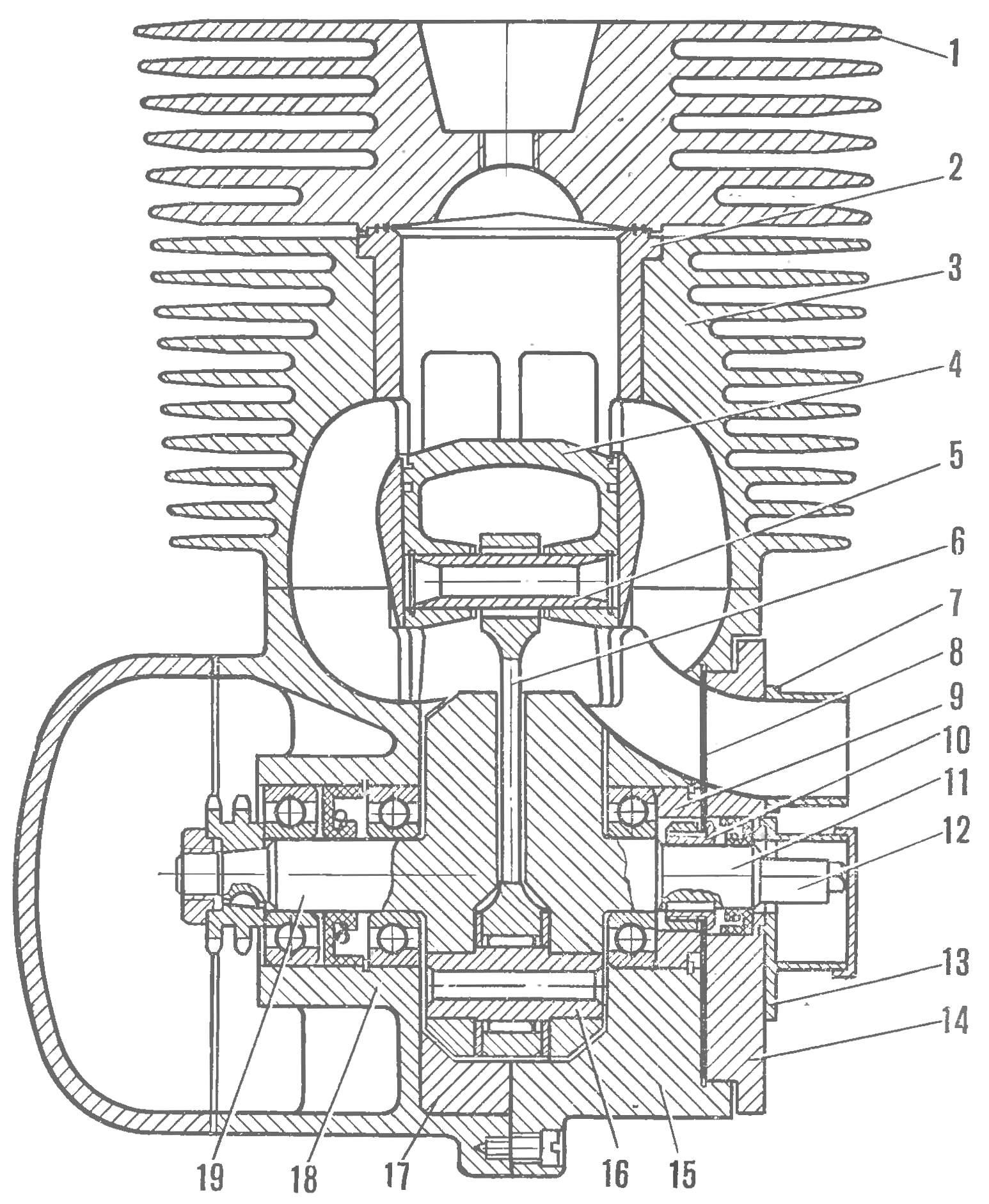
Fig. 1. The motor section (rear view):
1 — cylinder, 2 — sleeve; 3 — shirt cylinder; 4 — piston; 5 — finger; 6 — rod; 7 — a branch pipe of the carb, 8 — valve; 9 — spacer; 10 — bushing mount valve; 11 — the right half of the crankshaft; 12— Cam of the circuit breaker; 13 — the case of the circuit breaker; 14 — cover Zolotnik camera; 15 — right half crank chamber; 16 — finger of the crankshaft; 17 — ring crank chamber; 18 — the left half of the crankcase; 19 — left side of the crankshaft
The crankcase is subjected to significant alterations. From the mating plane of the cylinder left half of the crankcase was cut to a size of 79 mm, measured from centre of bearing seats of crankshaft (Fig. 2). New the mating plane should be strictly parallel to the old one.
Around the neck of the cylinder on the left half of the crankcase (where indicated by the arrow) is welded aluminum alloy in such an amount that the gasket manufactured according to the specified in figure 3-dimensions of its left half everywhere relied on the metal. The welding should preferably be carried out using argon-arc welding machine. Then milling it is necessary to align the mating plane of the cylinder.
In the crank chamber of the left half of the crankcase pressed into the ring made in accordance with figure 4. The place of its installation is shown in figure 2. It is sometimes necessary to pre-machined crank chamber on a lathe to give it the correct geometrical form. In order to avoid turning ring is fixed with two screws M5. Part of the ring, protruding into the neck of the cylinder, is removed by using a boring head on a milling machine.
Both the plane of the connector converted the left half crankcase it is necessary to grind on the iron plate. Satisfactory is considered to be such a plane, which, being washed from lapping powder, it has a smooth matte surface and controlling the movement of the plate touches it in all points.
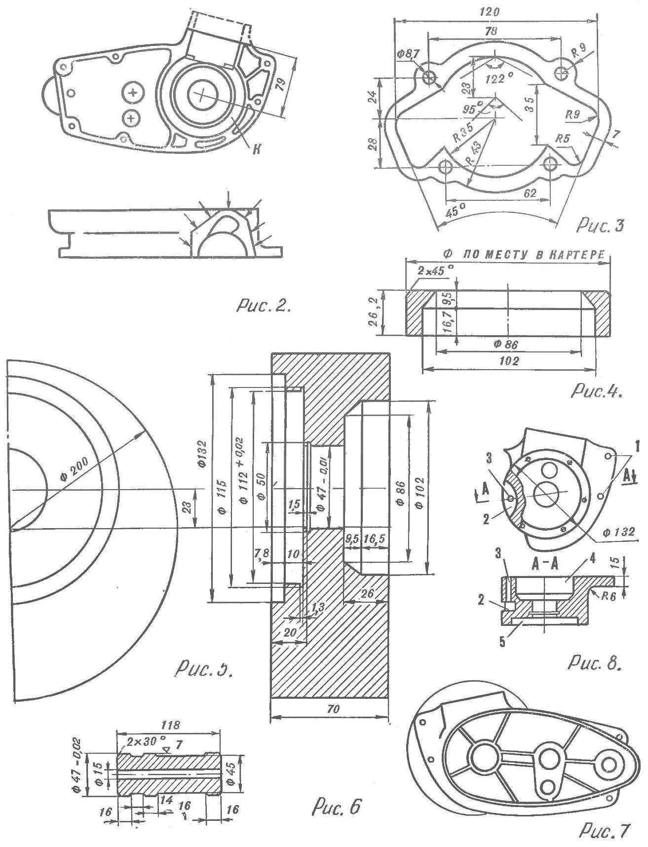
Fig. 2. The left half of the crankcase after revision:
To — push-ring crank chamber
Fig. 3. The gasket of the cylinder.
Fig. 4. Ring crank chamber.
Fig. 5. Harvesting the right half of the crank chamber.
Fig. 6. Caliber.
Fig. 7. The left half of the crankcase, combined with the blank right half of the crank chamber (left side view).
Fig. 8. The right half of the crank camera:
1 — socket rails; 2 — niche; 3 — hole stud; 4 — crank camera, 5 — slide camera
Then use a drill it is necessary to work on the lower part of the overflow channel. The shape of its cross section is marked with a gasket (see Fig. 3). The channel must begin from the cylindrical part of the surface of the cheek of the crankshaft and having in the vertical plane a smooth radius of curvature (see Fig. 1).
From the standard of the right half of the crankcase is used only a part serving as a cover for the transmission. The crank chamber is cut in such a way that its rear panel, which is simultaneously the front wall of the gearbox remains with a lid. Separate gear box cap and the right half of the crank chamber allow the development and adjustment of gearbox without opening the crank chamber.
The right half of the crank chamber is made of aluminum alloy D16. First on the lathe machined part in accordance with figure 5. For mutual alignment of the halves of the crankcase will need a caliber (Fig. 6) of steel of any brand. Inserting it in the bearing sockets of the two halves of the crankcase, connect them, and right cranks on the caliber to the position shown in figure 7. Then outline the contour of the left half on the right, after which the excess metal frezeruyutsya.
Side crank chamber adjacent to the cover gear box fitted in place in such a way as not to interfere with its installation. Frezeruyutsya also, the metal around Zolotnik camera, as shown in figure 8.
The right half of the crankcase is fixed relative to the left by means of two guide sleeves, which are drilled through holes (Fig. 8, 1) using the old holes of the left half. Both of the case screws are tightened, are located in the places provided by the plant to the left half. To ensure the necessary sealing of the crank chamber in its part adjacent to the transmission, install the stud with M6 thread, which zavertyvanija in the left half of the crankcase through the crank chamber. In the right half for the pin provided for the hole 3; niche 2 — nuts for studs (see Fig. 8).
After the work in the right half rastaquouere the neck of the cylinder, and the above-described methods produced lower part of the right waste window.
The right half of the crankcase lapped at the parting plane of the crankcase. After connecting both halves, and lapped the mating plane of the cylinder. The location of the studs of the cylinder are marked on this plane through the pre-drilled holes in the shirt of the cylinder.
In the right half and the cap of the valve is the inlet channel (channel shape and its location are visible in figure 1). The upper edge of the side channel Zolotnik camera should defend from its outer edge at 3— 4 mm, and the lower flange 2— 8 mm above the edge of the slot of the crankshaft bearing. The channel should be aligned in the cross section of the flange of the carb and a few to expand (in horizontal section) at the entrance to podpisnoe space.
CRANKSHAFT
Basic elements it is made in accordance with figures 9-11. The halves of the shaft, the rod and finger of the lower connecting rod is made of steel 12KHN3A, their working surfaces are subjected to carburizing to a depth of 0.8— 1 mm. the Surface of the holes of the heads of the connecting rod and the finger are hardened to a hardness NIS = 60-63 units.
Surface holes for the finger and the surface of the crankshaft pins have hardness of HRC = 42-45. After heat treatment all the working parts of the shaft is polished and adjusted to the desired purity and size.
In the lower bearing geniculate used the separator made of duralumin alloy D16T, and fourteen rollers of Ø 3 mm and a length of 11.75 mm. Between the connecting rod and the cheeks of the shaft on your finger has two freely rotating polished washer steel U8A thickness of 2 mm each. Washers have a hardness of HRC = 59— 62. Finger connecting rod is pressed into the holes of the halves of the shaft with an interference fit 0,11 : 0,13 mm. Radial clearance in the bearing-connecting rod — 0,009 : 0,011 mm axial and 0.5 to 0.6 mm.
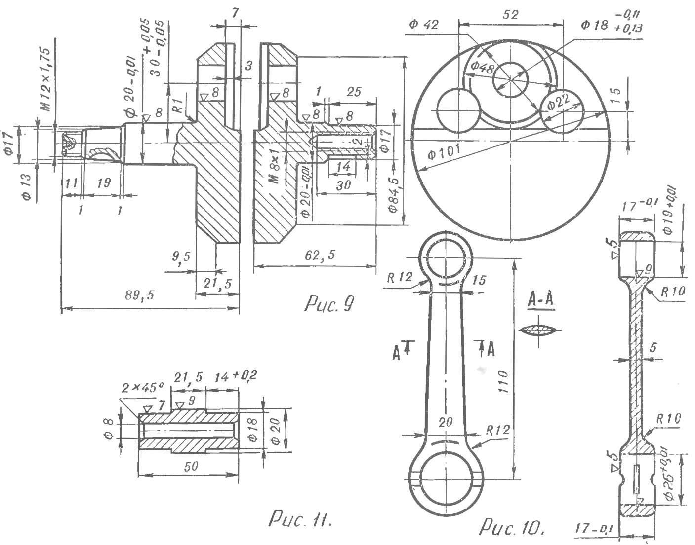
Fig. 9. Crankshaft.
Fig. 10. The connecting rod.
Fig. 11. Finger.
The coefficient of balance of the shaft chosen for the momentum close to the maximum of 0.65. (Measurement of the coefficient of balance crankshafts racing engines can be found in the book by A. N. Silkin, and B. S. Karmanova “Manual of motorcycle mechanics”, Publishing house of DOSAAF, 1970)
To obtain the desired ratio balance balance holes in the cheeks of the crankshaft are filled with tubes of aluminum or magnesium alloy, or caprolon. Selection of material with different specific gravity will allow you to compensate for possible errors in the balancing made during the manufacture of the balancing holes in the cheeks of the shaft.
In the upper end of connecting rod-used needle bearing without cage, with needles Ø 2 mm and a length of 17 mm. Axial displacement of the needles ±1 mm is limited by hardened washers of steel U8A 1 mm thick, loosely fitting the piston pin. The radial clearance in the bearing upper connecting rod of 0.01 ÷ 0.015 mm. Piston pin 15 mm diameter used from a motorcycle “IZH-Planeta”. Finger cut the length to size 52 mm.
(To be continued)
Recommend to read
 THE CRUISER-LIKE SHIPS, AND SHIPS-CRUISERS
Two decades on the verge of XIX and XX centuries were years of turning the cruiser into a real fighting machine. Continuously growing sizes; armored vehicles gave way to armored, the... CRAB: A COLLAPSIBLE BOAT
The proposed design is a four-section, three-man boat with load capacity of 320 kg In tourist trips she, being dragged to the Bank, turns in a fairly spacious "tent", especially if you...
