Since the pedal drive is mounted on the axis of the machine and the driving wheel (rear right), could not dispense with the intermediate gear. For her adapted sprocket — all from the same bike “Space”. Large (20-bevel) sprocket welded directly to the intermediate shaft. Another small sprocket (z = 16) of the transmission — planted on the intermediate shaft via a steel hub to which it is welded, and the hub attached to the shaft with cotter pin. Sliding bearings, in which rotates the intermediate shaft, first made of nylon, and when they are in the service>-u worn out — replaced by PTFE. The supporting brackets of the intermediate shaft bolted to the MB welded to the frame plates with longitudinal grooves. These longitudinal slots are used for tensioning the chain first stage of the drive. The circuit of the second stage is tensioned by means of PTFE roller mounted on podroikina the lever, cut off from the pedal rod of a Bicycle. The sprocket drive wheel is also taken from the old children’s bike.
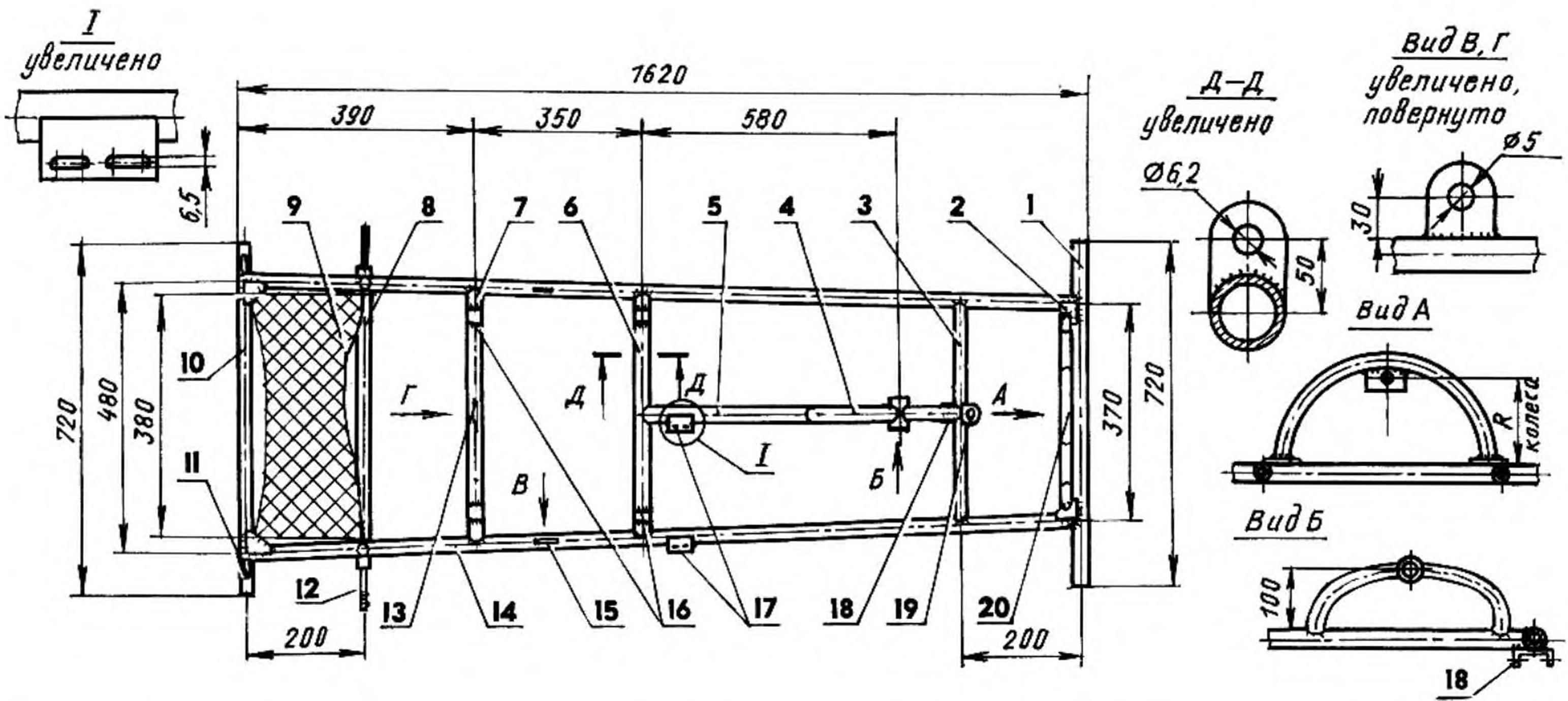
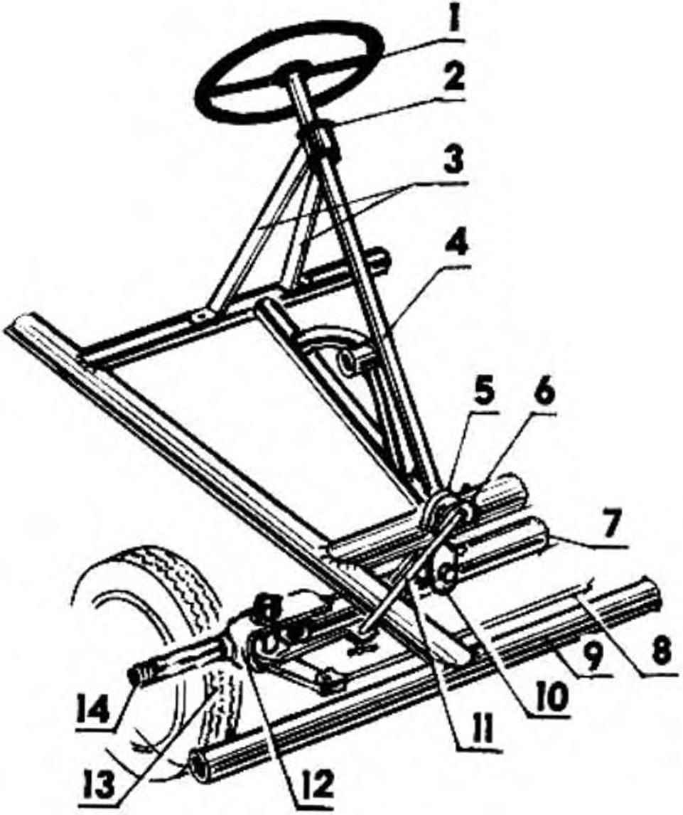
Frame and rear axle (all items, except where noted, are made of tubes of Bicycle frames):
1 — front bumper;
2 — Klondike solitaire (STZ, the sheet s3. 4 PCs.);
3 — front cross member;
4 — stretcher of a pedal of a drive (from tricycle “Space”);
5 — medium insert;
6 — middle crossbeam.
7 — rear cross member;
8 — rear axle beam (water pipe 1/2″);
9 — the passenger (corrugated steel sheet s2);
10 — rear bumper; 11 — bushing braking device (water pipe 1/2″);
12 — the axis of the rear wheel (STZ, round 22, 2);
13 — bracket of a braking device (sheet s3);
14— bulkhead (2 PCs.);
15— eyelet cross-rope braking device (STZ, sheet z, 2); 16 — mounting brackets seat frame (channel № 2,5, 4 PCs.);
17 — mounting bracket supports the intermediate shaft (STZ, sheet s3);
18 — eye of the hinge suspension front beams (channel № 5,5);
19 — bracket steering shaft (STZ, sheet CI);
20 — subframe and the bracket zapasnoy wheels.
Beam front axle is made of half-inch plumbing pipe and made a swinging. Its connection with the frame carried by only one of the hinged bracket in the middle. This suspension bridge eliminates the stuck on rough road not only one of the front steering wheels, but that pajupuu, more importantly, leading the rear. One part of the hinge is a welded girder of bridge steel bushing with PTFE sliding bearing inside. The second part is a bracket in the form of an eye; it is welded to the crossmember of the frame. Both parts of the hinge (and consequently the front beam to the frame) are connected by a axle-bolt M12.
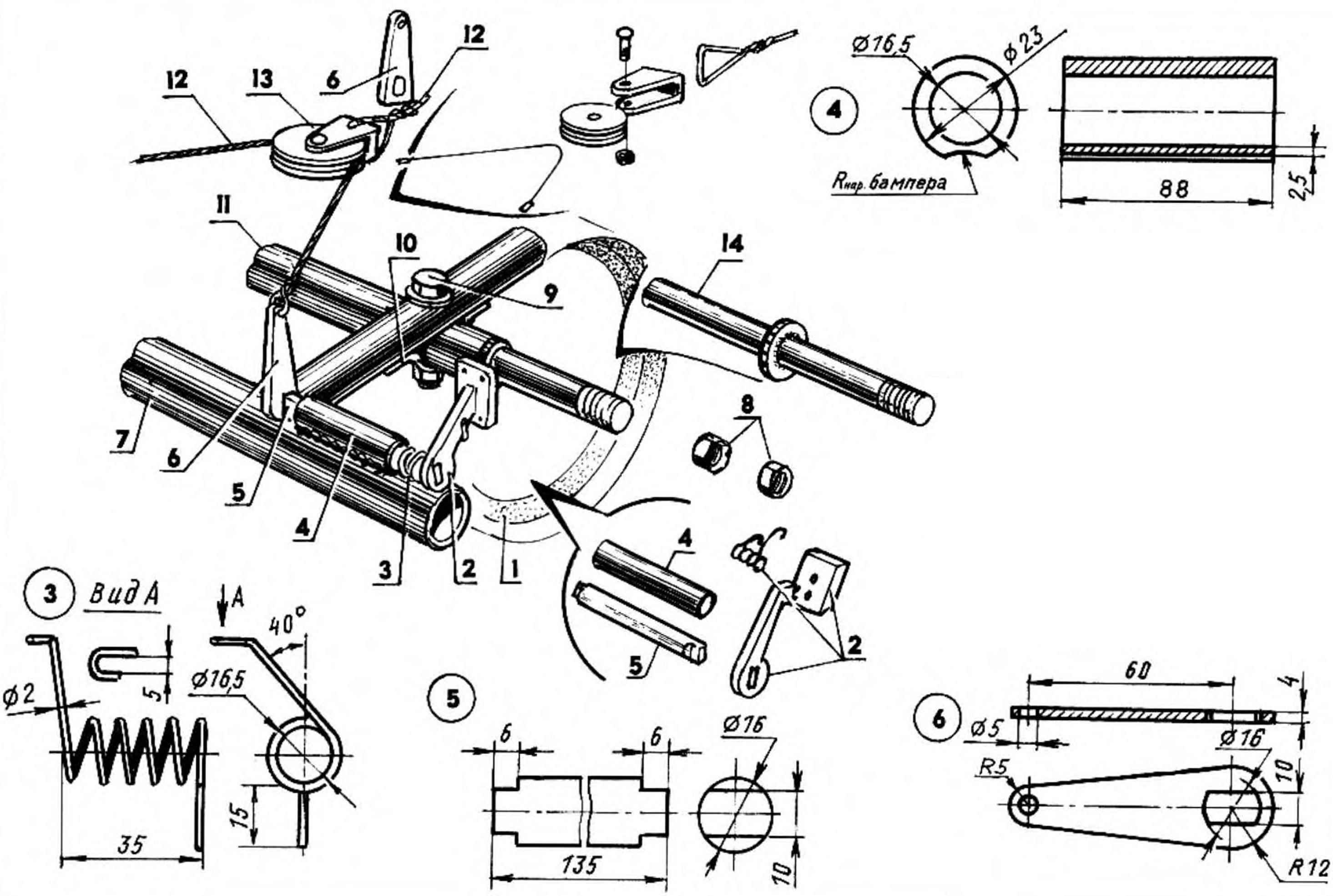
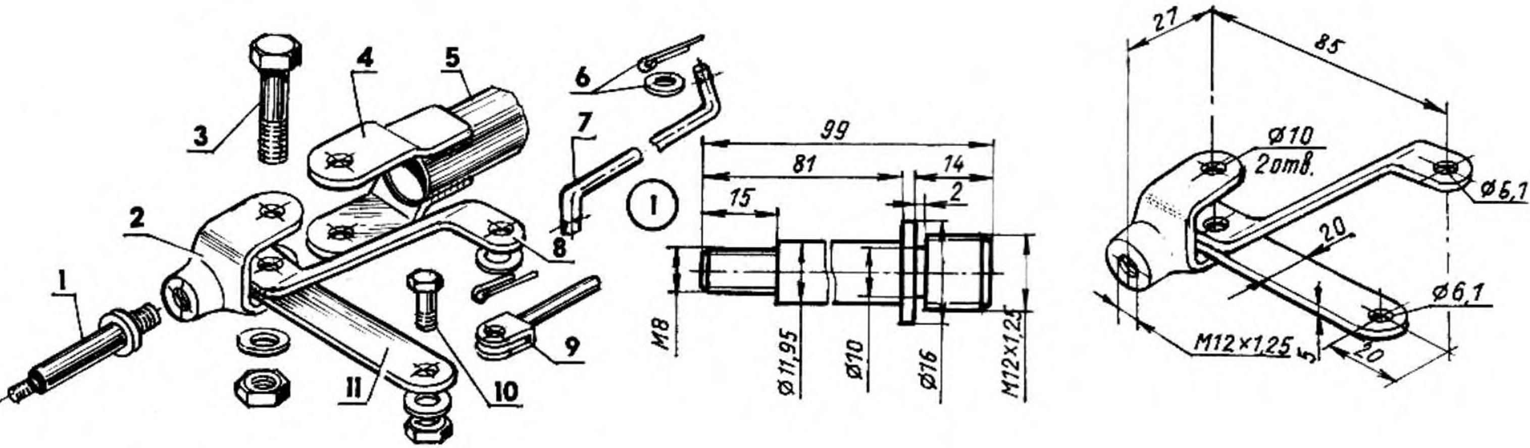
Rear axle with wheel and brake device:
1 — wheel (from a child’s Bicycle);
2 — brake pad;
3 — spring return left and right mirrored (wire Ø2);
4 — bushing (water pipe 1/2″);
5 —brake shaft (St 45, range 16);
6 —brake lever (STZ, sheet s5);
7 — bumper (tube from the frame bike);
8 — nut M8;
9 — bolt M6;
10 — clip (STZ, sheet s2);
11 — rear axle beam with axes (a water pipe 1/2″);
12 — the cable of the brake mechanism;
13 — block brake;
14 — the axis of the wheel.
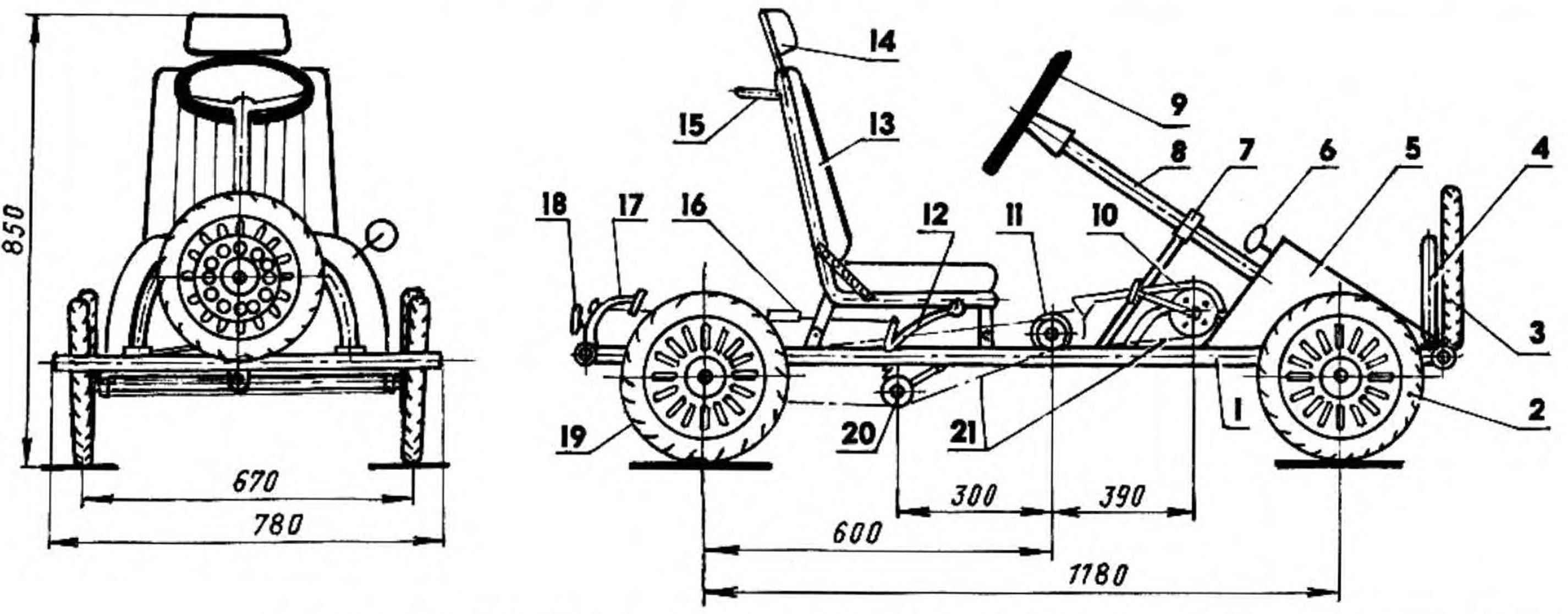
Steering is done according to the type of automotive. Bagel with a diameter of 300 mm is bent from a steel 10 mm rod and “covered with” a rubber hose. Steering shaft — cut half-inch pipe welded in the middle part of the thrust collar. The shaft is mounted at an angle of about 45° to the plane of the frame and secured to it two brackets using a nylon bushing. From the bottom of his pipe pressed on and welded the adapter to it is attached a Pitman arm. The latter is connected by a rod with a bipod knuckle right wheel, and the lever is this fist mikulasova rod connected to the knuckle of the left wheel. A Pitman arm is short, and therefore can be installed (to go) as standing up and down.
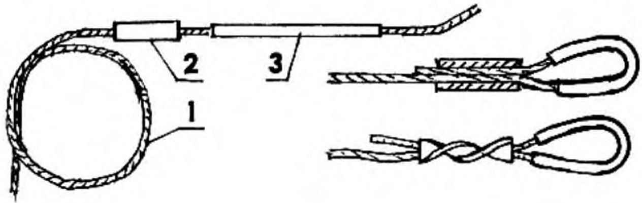
Making loops on the wire:
1 — the cable;
2 — bushing (copper tube);
3 — thimble (copper tube).
The steering knuckles are made of plugs threaded clevises from trucks. Forks at the cut ends, together with holes for the fingers and drilled the other, closer to the neck. To each fist are welded onto the levers, and more to the right and swivel bipod. These parts are made of steel strip section 20×5 mm.
Axles machined with the same thread on one end that thread into the end of the steering knuckle hole, where it is then it is injected and it can be controlled by the Kern.
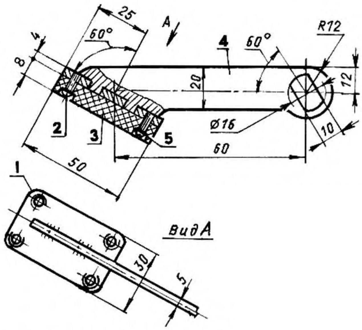
Brake lever with pad:
1 block (St3, sheet s4);
2 — screw M3 (4 PCs.);
3 — lining ( rubber, s8);
4 — arm ( St3, sheet s5);
5 — washer.
As the front wheels are used on the Cycling card front from children’s tricycles. Of them removed the pedal cranks and to the disk by eight bolts M4 attached machined steel hub. It is inserted from different sides, two nylon bushings (bearings) with the inner hole the same diameter as the wheel axle (12 mm).
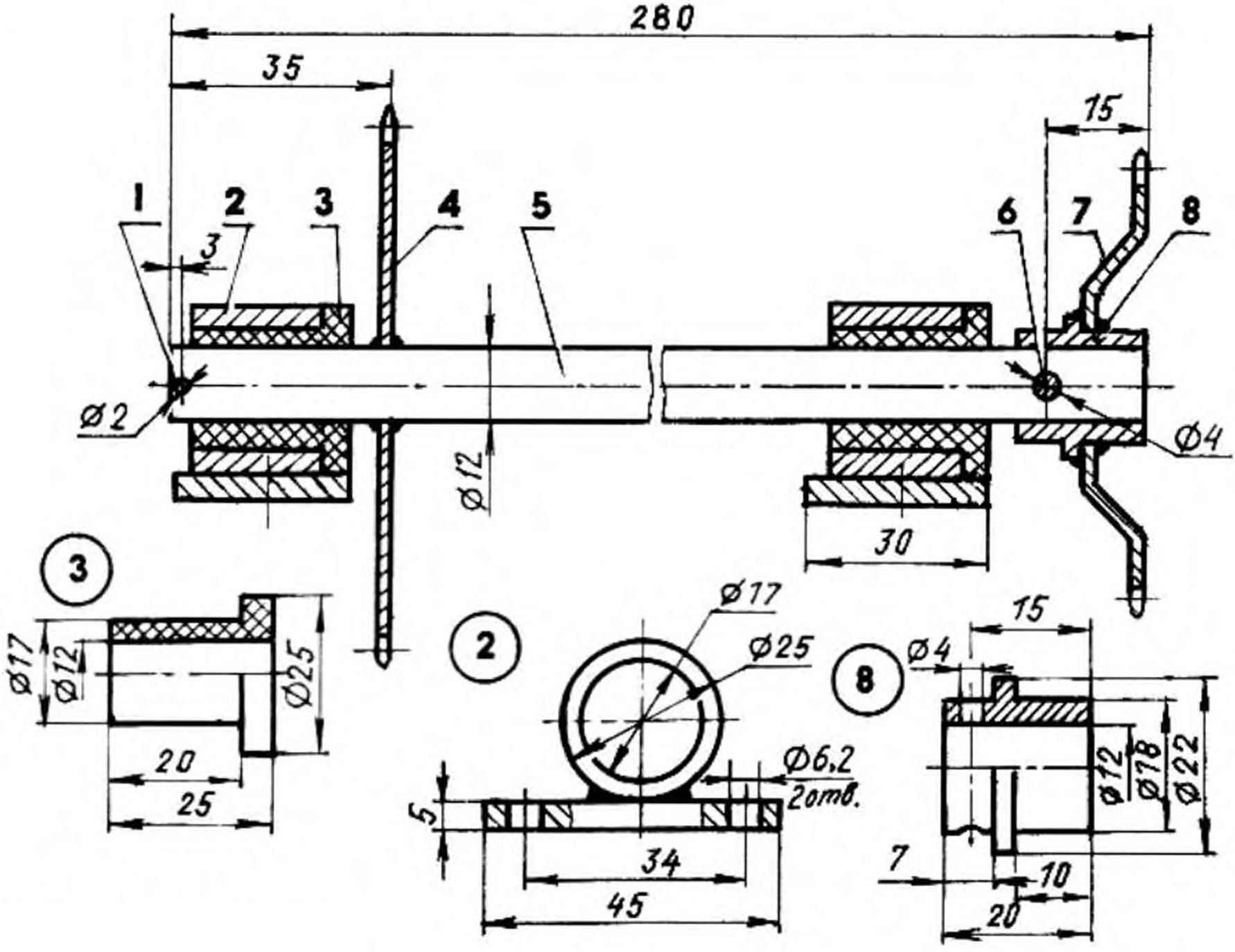
Intermediate gear:
1 — cotter pin Ø2;
2 — bearing (steel pipe 25х4, St3, the sheet s5, 2 PCs.);
3 — sleeve-bearing (nylon or Teflon, 2 PCs.);
4 — a large sprocket z=16 (of Detskoe bike);
5 — shaft (from a child’s Bicycle);
6 — pin Ø4;
7 — small sprocket z= 16 (children’s Bicycle);
8 — foot (ft3, round 22).
Beam rear axle, like the front, made of half-inch water pipe. At both ends it is pressed and welded axle wheels. Rear wheels are ready from the same children’s Bicycle “Space”. They diameter slightly larger than the front, but it kompensiruet level of the suspension beams.
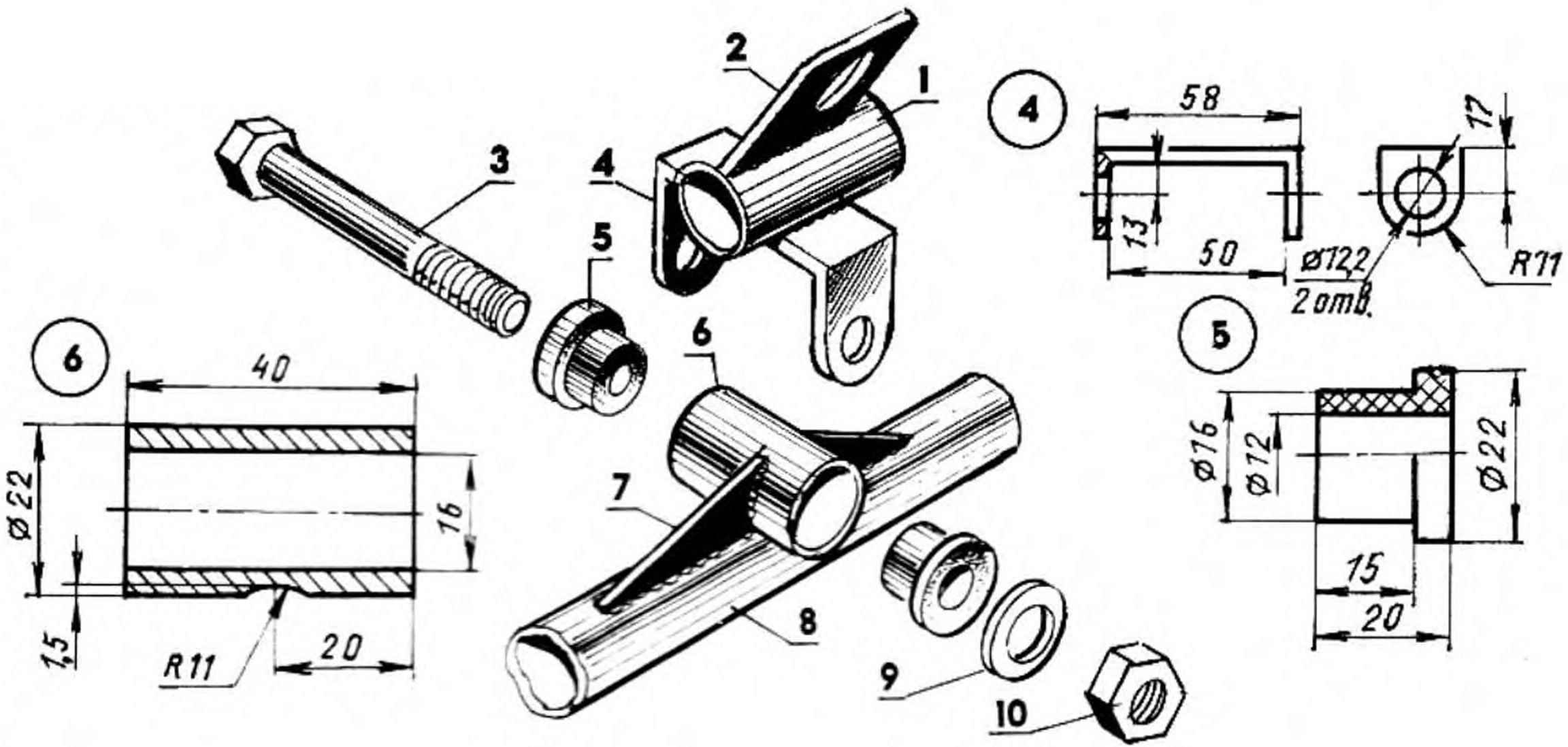
Joint suspension I-beam front axle to the frame:
1 — front cross member frame;
2 — lower support bracket steering shaft (St3 sheet s3);
3 — axis-M12 hinge;
4 — eye shamra (steel, Soler);
5 — Bush-bearing (Teflon, 2 PCs.);
6 — Bush-suspension Samra ( steel pipe 22х3);
7 — Klondike solitaire (St3 sheet s3, 2 PCs.);
8 — beam front axle;
9 — washer;
10 — nut M12.
Beam is inserted into the brackets of flat steel that is welded to the side members, and further attached to the frame with M6 bolts through holes drilled simultaneously in all parts of this site: rail, beam, bracket.
The knuckle guide of the front wheel:
1 — axis aprasymas wheels;
2 — fist (rod tip truck automoble, modified);
3 — axis steering knuckle (bolt M10 with washer and nut);
4 — lug steering knuckle to the front beam (St3 sheet s3, 2 PCs.);
5 — the front beam;
6 — split with washer (2 PCs.);
7 — miloskova thrust (steel rod Ø5);
8 — fry fist (St3, strip 20х5);
9 — mikulasova thrust with a tip;
10 — lever axle (M6 bolt with washer and nut);
11 — the lever(St3, strip 20х5).
Brake design is virtually identical to the one that was published in № 3, 1978, of the journal “modelist-Konstruktor”. Only in my version the brake is powered not by pedals, and the handle located on the right side of the seat.
Because this issue is unlikely to have survived even in library archives, it makes sense to give the drawings the brake mechanism and in this publication.
Steering:
1 — steering wheel (steel, circle 10);
2 — Bush (nylon);
3 — upper support bracket steering shaft (steel strip 20×3);
4 — steering shaft (steel pipe 1/2″);
5 — lower support bracket steering shaft (STZ, sheet s3);
6 — a Pitman arm;
7 — beam front axle (rough plumbing 1/2″);
8 — mikulasova thrust;
9 — frame;
10 — joint suspension I-beam front axle;
11 — pull the bipod;
12 — a rotary fist;
13 — front idler right wheel (from a child’s Bicycle);
14 — the axis of the guide peredney right wheel.
And the last one. The seat is made based on the tubular frame of the driver’s seat of the truck, “Colchis”. Maybe this frame and heavy, but durable. At the top of the back part of frame welded passenger grab handle. The backrest and seat form plywood sheets, laminated foam and covered with leatherette. To the frame of the EuroVelo map frame of the seat is attached by brackets at four points.
Recommend to read
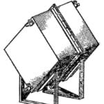 POURS MEMBRANE
Experienced gardeners watering the beds in their gardens and backyards only warm water supernatant. To do this, they fill placed on the site of the barrels in the morning and consume the...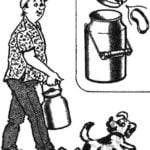 QUIET CANS
Metal household cans is reliable and durable, comfortable and even aesthetically pleasing. The only drawback to some of them — loosely cover, why when you walk you hear an annoying...
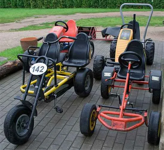
 A few years ago for her sons made a small recumbent (and judging by the size or design — it would be more accurate to call it melakarta). Children machine like, and they, along with the neighborhood kids for hours chased her down the quiet streets.