 Existing models of walkers have several major disadvantages: the speed of these machines is usually not more than 8-10 km/h; they move irregularly or are experiencing vibrations in the vertical plane; walking mechanisms are mutually unstable.
The solution of these problems will allow you to create a new kind of transport capable of moving on any road newly developed areas, to overcome descents and ascents of up to 45°.
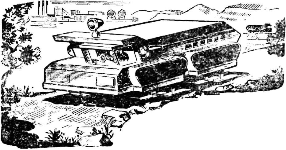
Walking machine can be used for the carriage of ore, coal from open-pit mines, the construction of Foundation pits for power plants, roads and other structures. Technically the real construction of the walkers with a capacity of 100 tons and more.
Spend some comparison, wheels, caterpillars and walking mechanism when driving on rough terrain.
In figure 1, the wheel rolls over a bump of height “a”. Part of an obstacle “B” “enter” in a pneumatic tire wheel axle, rise to the height “B” and the center of gravity of the machine rises to a height of “G”. Tire made of reinforced rubber, the difference between the strength at deformation and return to its original position big.

Fig. 1. The scheme overcome the irregularities of the road wheel, a caterpillar and a support mechanism walking.
When rolling the wheels along the soft road to deform the soil. It also takes more energy. So, when you move a wheeled tractor on plowed soil moist to the soil deformation takes more than half of the energy delivered to the wheel.
Now consider a caterpillar mover (Fig. 1). It has ribbon hinges, United with your fingers. When she falls on hard obstacle, as shown in the diagram, the track link up. Rollers, passing through the raised parts also rise, partially compressing the springs of the carriages; the ascent of the center of gravity of the apparatus, which requires extra power. A significant energy loss caused by friction in the open joints, which have increased wear.
From walking mover support surface are “ski”, which may have a rubberized bottom surface. When this wad is getting on uneven ground (Fig. 1) it relies only on the tops of the protrusions. All of the projections and recesses of the ski are not copied. Therefore the centre of gravity of the machine from the roughness of the soil within the length of skis varies.
In walking mechanism of the “leg” in the lower position should move in a straight line with constant speed. These conditions are well maintained in the mechanism of P. Chebyshev (see Fig. 2).

Fig. 2. The basis stepantsova device — a mechanism P. Chebyshev.
Upon rotation of the crank the point a moves in the upper part of the trajectory on a curve with a variable bottom in a straight line with constant speed.
Walking in the proposed mechanism (Fig. 4) the problem of movement and stability is solved by the fact that the “Pramila” P. Chebyshev added double parallelograms that create the same curve in the same plane as the point a, only with a displacement in the direction of motion. The stability of same “legs” is the fact that it has a hard top mount, bottom — large enough bearing area.
But to move one leg a little. Therefore, in one case, replacing the wheel, you need to install the two-step mechanism (Fig. 3). When the total rotation of the crank B and B1 move along the same trajectories, and that when one “leg” is still not away from the surface, the other is based on it.

Fig. 3. Diagram of the walking mechanism with two “legs”.

Fig. 4. Schematic diagram of the walking mechanism and the calculation of leverage:
1 — crank 2 — 6,8 — levers, 7 — “up” 9 — body frame, 10 — pole; dimensions of the levers 2, 3, 6 8 — depend on the radius of the crank of the Calf; the size of the levers 4 and 5 are arbitrary, but equal and the distance “A” between the axes of the levers 8 and 3; R is the distance between the axes of the lever 3 and crank the same 2Rкр; the length of the “legs” are arbitrary, and her step equal to four radii of the crank.

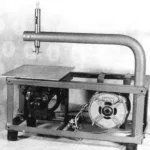
Fig. 5. The schema model of walking machine built in CSUT of the RSFSR:
1 — platform, 2 — engine 3 — clutch. 4 — the mechanism of “walking”, 5 — pole “legs.”
Model Walker made on a tracked vehicle. One caterpillar is replaced by a walking-beam mechanism with two “legs” in one case. The rotation is carried out by the difference in speed of opposing pairs of “legs”. The crank radius is equal to 10, see models built in CSUT of the RSFSR, is the electric motor supplied from the network 220, and rotation transmission from him on the walking mechanisms of the automatic continuously variable transmission with independent drive for each pair of “legs”. This device automatically adjusts gear ratio depending on the load during movement of the Walker. The engine always runs at the same speed, the load on it is constant, independent of the load on the legs.
To ensure the stable equilibrium of the system and to eliminate oscillations of the center of gravity of the walking machine has four pairs of “legs”. Each pair is always in the opposite state, so on earth there are always at least four “legs”.
Each mechanism of the two “legs” attached to the body using elastic knot (spring, pneumatic cushion). The surface of the base of the ski can be big, so the machine vibration from the roughness of the soil as the wheels are missing. The position of the arms, and “legs” are always mutually opposite, so the system is completely balanced.
A. POPOV, head of the laboratory of experimental csyt transport of the RSFSR


