WAVING THE STEERING WHEEL

BEATING THE WHEEL
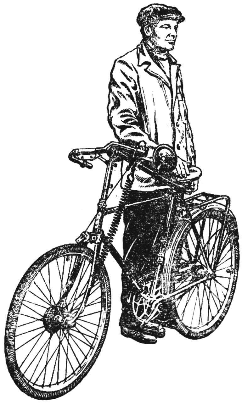
The first test of this bike took place at night. And the winter. And if the first can be explained by the unusual design, then the second — just looking forward to the author’s development: why wait for spring when the snow tract is not worse than asphalt, and test the idea and want their case immediately. Therefore, hardly any of the villagers Dyakonov, in the Tula region, saw the frosty January night their countrymen Ivan Zabashta rolled out and “straddle” the bike. Yes, if I saw anything unusual I would not have noticed. Except for one strange behavior of the cyclist. And indeed, as if testing or demonstrating remarkable strength, he “bent” the wheel down, then unbent his horns, lifting them up. However, not tested the power, and the new manual transmission of the original design, in which I. A. Zabashta tried to avoid many of the shortcomings of other well-known schemes for the transmission on a front wheel. How managed it, tell the author.

It all started with the publications of “M-K” on additional hand drive the bike on the front wheel. The idea itself is very tempting: to win to force on the hard sections of the road while climbing a mountain; to eliminate the passivity of the hands while riding.
 
However, when I decided to do something similar for your bike, could not give preference to any of the schemes that each had serious deficiencies. Take, for example, the variants which are based on manual drive Dutova — with spinning rods. In essence, it is mechanical shifting on the front wheel of an ordinary chain drive to the rear wheels: the same sprocket, pedals, chain. Only the drivetrain is mounted not horizontally but vertically, along the steering column and forks. Those who use this scheme, you know its weaknesses. And above all: to turn the hand cranks simultaneously to control the bike even on the slightest turns very difficult. In addition, the maximum force from hands is removed only when driving them forth from himself, and that if the saddle is equipped with a back — stop; the action of the hands and feet are not interconnected, there are no conditions for a full merger of the applied forces. Not areas where manual operation is not needed, it is compared with the wheel awkward to control. Not helps and a combination of steering and connecting rod drive.
Somehow it appeared in the magazine description suspension wheel-drive Egorova. I decided to recurrence. But the test of the anointed that bike with such a drive is fairly unstable, not to mention the complexity of the design. However, this scheme gave me an idea how to avoid these drawbacks.
 
Fig. 1. Diagram of manual transmission
 
Fig. 1. Diagram of manual transmission:
 
1 — rear wheel as-front, 2 — block and band spring, 3 — intermediate scivac, 4 — wire actuator, 5 — stop, 6, 10 — leverage steering, 7 — polysester, 8 — brush, 9 — stirrup, 11 — mirror, 12 — spring-energy accumulator.

 
Fig. 2. Hinge joint of levers of the rudder (the position of Fig. 1).
 
Fig. 2. Hinge joint of the steering levers (the position of Fig. 1).
 
Fig. 3. The scheme of combs and stapes.
 
Fig. 3. The scheme of combs and stapes.

 
Fig. 4. Sealing of cable on the block.
 
Fig. 4. Sealing of cable on the block.
 
The main idea was as follows: the need to leverage the drive was not swinging, and “flapping” movement, that is, lowered or raised simultaneously and locked in the horizontal position — served as bi to all of our usual comfortable driving.
 
Already the first version has found approval and support at the office. Inspired by this, I in the course of a year improve and optimize the design and finally decided to take her to the readers: I think it is something that can be taken as a basis and developed further.
 
How is flashing the drive?
 
It levers horns-the usual steering, cut off from the steering column and modified in accordance with the new functions. Are welded thereto hinge bushings and polysester mutual engagement, providing a simultaneous “strokes” half helm, becoming henceforth and levers of a drive on the front wheel. The transfer is not a chain and lock through the intermediate pulley on the main unit front wheel, performing a reciprocating rotary movement. As the front wheels used the rear, which instead of the asterisk box is underneath the cord.
When you “swing” the rudder goes up idling drive: freed from the tensioning cable under the action of a tape spring wound on the power wheel. Back to “swing” the rudder down, in addition to the efforts of owner, helping coupled with one of the levers spiral spring. Stretching up, the cable causes the spin block, and through him to the very front wheel. The rhythm of swing of the rudder can be selected freely, depending on their own capabilities of a cyclist and road conditions. On difficult sites and upgrades could double the included traffic for the effort — due to the simultaneity of the pressure foot on the pedal and squeezing the hand levers in the down position. In addition, the point of attachment of the cable to the lever can change on the go. It is so. Welded to the end of the lever comb a special stirrup — place cable mounting. Moving the stirrup at the time of idling, we change the shoulder, and hence the applied force.
 
Fig. 5. Revision separator sleeve
 
Fig. 5. Revision separator sleeve:
 
1 — separator 2 — soldered the hook (under the spring).
 
Fig. 6. Revision of the cone bushings
 
Fig. 6. Improvement of cone bushings:
 
1 — cone, 2 — soldered a bushing with a hole (under the spring).

 
Fig. 7. Chart movements comb lock
 
Fig. 7. Diagram of the movements of the comb cable lock:
 
A — position for the highest gear ratio, B—for the smallest (A1, B1 — for the lower position of the lever steering).

 
For the manufacture of the actuator was used most of the finished items: different kinds of bicycles, cars and motor vehicles. Thus, the hinge part of the levers are assembled from the elements of the steering column and front fork of an old Bicycle is bushings, bearings, housings. The bushings are welded, respectively, modified gear from parts of a motorcycle: they dispersed Inner diameter (for plugs) and made a cutout for the fixing by welding of the ends of the halves of the wheel.
As already mentioned, is the front wheel set back, the separator in its bushing is made spring-loaded. For this, he protochen and it soldered the hook, and the Konus — sleeve with holes; the hook and the holes serve for fastening the spring ends of the separator. Instead of the sprocket to the hub is attached to the block underneath the cord — modified stamped pulley from the vehicle. It Ø 90 mm, outer — 120 mm Through the hole in the side of the block is passed a rope, the ends of which are then woven and attached to the stapes. To rotate the block, against the direction of the wheel and spin the cable at idle levers handlebar tape serves as a spring motor taken from the kickstarter. Another spring in the drive — spiral — mounted but the second lever steering. In the horizontal plane both halves steering fixed due to the special emphasis which is spring-loaded and automatically retracts when moving the lever up.
 
Appearance hand drive.
 
Appearance hand drive.
 
Here is a chart of the provisions of the cable when movement of the stapes at the comb allows you to calculate the gear ratio and the desired diameter of the block. I was taken ready-made unit with the working circumference (the length of the coil cable ka) equal to 280 mm. Is the same distance A—A1 chart, that is, the gear ratio is 1.0. This means that while the stirrup in the first position when the shift lever with the comb up the block (and with it the wheel) will make one complete revolution. The opposite extreme position of the stapes changes the relation: section B—B1 is equal to 170 mm, respectively, the gear ratio will be: 170 : 280 = 0,6.
 
In conclusion, two background size: the diameter of the front wheel 720 mm; the distance from its axis to the centers of rotation of the steering levers is 820 mm.
 
I would be happy if my drive to someone will serve in good stead, and even more if someone will develop the idea further improve the design in their own way. I wish this theme was continued in the pages of “M-K”, which helped me so much.
 
I. ZABASHTA

Recommend to read

  • REACTIVE FIRSTBORNREACTIVE FIRSTBORN
    THE F-80 SHOOTING STAR. The story of the creation of the F-80 started in late spring of 1943 at Wright field, where the main designer firms Lockheed (Lockheed), Daniel Russ (Russ Daniel)...
  • GENUINE RUSSIAN NAVYGENUINE RUSSIAN NAVY
    The victory over France in the war of 1870 opened to the Federation of German States, formed under the auspices of Prussia, a completely new Outlook In Central Europe is variegated...