
 Unfortunately, experience manufacturing propellers for the Amateur designs with rare exceptions not worth repeating. And perhaps the main cause of failures in the inconsistency of the parameters of the propeller with the engine performance. Often Amateur designers create too “heavy” in the wind against the propellers, causing the engine not developing full power and thrust is insufficient.
The proposed method of determining geometric parameters of the propellers allows to simplify the task of the selection of their dimensions, thereby providing relatively high efficiency, the ability to more fully exploit the engine power.
With the design of air screws should be borne in mind that the thrust of the screw when properly selected step and the cross sections of the blade depends on its diameter and power on the shaft (see Fig. 1). The maximum allowable diameter is determined by the figure 2. It is limited, in addition to structural considerations (increase in diameter increases the size of the machine) mainly peripheral speed of the end blades: for screws with wooden blades And curve, metal curve B.
The excess of the peripheral speed in excess of the recommended causes the wave resistance due to the compressibility of air, drastically reducing the efficiency of the propeller and substantially reduces the margin of safety because of the increasing centrifugal forces.
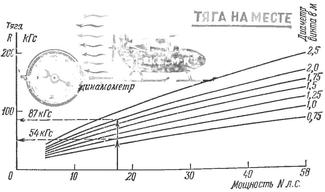
Fig. 1. The chart of interdependence between the screw diameter, power, and traction.
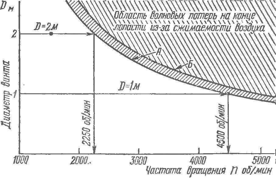
Fig. 2. The chart of interdependence between the screw diameter and the frequency of its rotation.
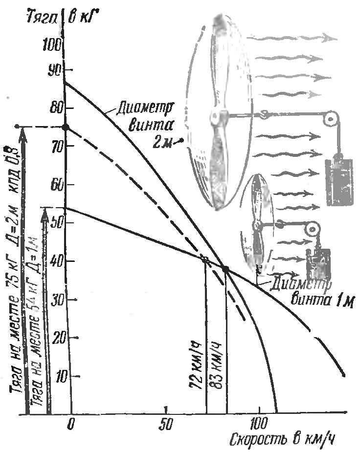
Fig. 3. Thirst for speed for power 17,5 HP (screws with a diameter of 1 m and 2 m).
According to figure 2 for the selected diameter of the screw you can determine the maximum frequency of its rotation. For example, if the engine develops its maximum power at 4500 rpm, it is necessary to choose the diameter of the propeller 1 m, or if the propeller thrust with Ø1 m is insufficient, install the screw with a larger diameter and a reduction gear. When you install gearbox, you should consider its efficiency: the power supplied to the propeller is reduced by the amount of losses in the transmission. Values of efficiency are as follows: single-stage gear transmission with spur gears (cylindrical) is equal to 0,99; with a spur bevel gear — 0,98. It should be noted that the efficiency of the gear transmission decreases with the decrease in the accuracy of its manufacture and Assembly, reaching up to 0.94 and even to 0.9.
Efficiency of belt transmission — in the range of 0,95—0,97; chain — 0,94—0,98. If transmission efficiency taking into account friction in the bearings is equal to 0.9 to 0.8, then the thrust will be (respectively) 0,94—0,86 from the thrust, defined in figure 1. With the increase of travel speed tractive effort of the propeller decreases. Depending on the diameter and the pull speed is changed variously. Figure 3 shows the change in thrust for speed propellers with fixed pitch No. 1 Ø 1 m and No. 2 Ø 2 m, at a constant power of 17.5 HP On the chart shows the advantages of the thrust of the propeller from 02 m, up to a speed of 83 km/h, while the transmission efficiency of 0.8 to a speed of 72 km/h At a speed greater than the specified has the advantage of a screw Ø1 m. With a headwind of 10 m/s (36 km/h) advantage screw Ø 2m remains up to speed, the smaller the magnitude of the wind speed, i.e. up to 36 km/h.
The example gives a visual representation of the interdependence of the screw diameter, the translational speed of the vehicle (at constant power) and develop them traction. For propeller planes and gliders with low speed, the calculation is recommended for the operating conditions of the screw in place, i.e. for V = 0.
The next step in the design is the determination of the width of the blades, their number, profile, blade section and angle of its installation (step). These parameters should be linked with the selected diameter, the rotating speed of the screw and power on its shaft. In practice, rarely found the need to use complex aerodynamic configuration of the screws with the large air load on the blade section, that is section with a large curvature and a slotted section. The vast majority of screws that are optimal for the given requirements, will have a narrow blade and standard wing profiles.
In the above chart (Fig. 4) it is possible to determine the geometrical parameters of the screw, which is consistent with the characteristics of the engine. Depending on the propeller diameter and the power on the shaft is determined by the rotation frequency corresponding to the selected relative to the width of the blade (in percentage of the radius of the screw). On the same graph is the pitch, related to diameter H/D (relative pitch) that is optimal for a selected width of the blade.
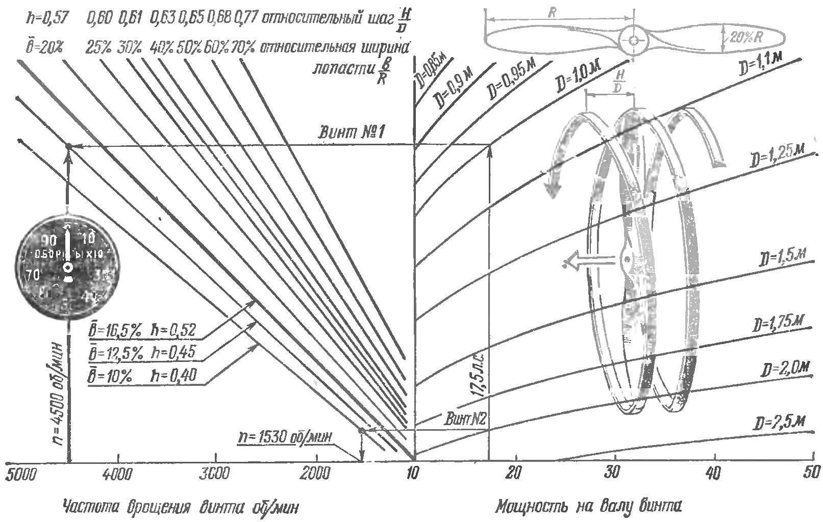
Fig. 4. Definition of the possible geometric dimensions of the screw rpm and motor power.
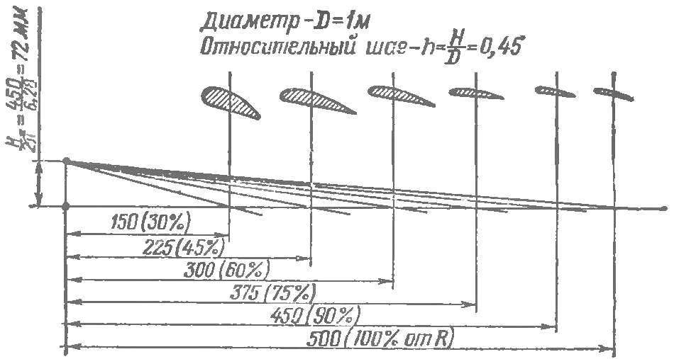
Fig. 5. An example of the construction of the angles of the cross sections of the propeller blades with a constant pitch. Diameter 1 m, the relative step h=H/D=0,45.
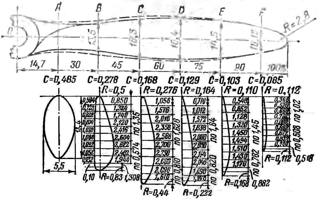
Fig. 6. The geometric dimensions of the blades of two-bladed propeller (percentage of radius) when the width of the blade is 16.5%.
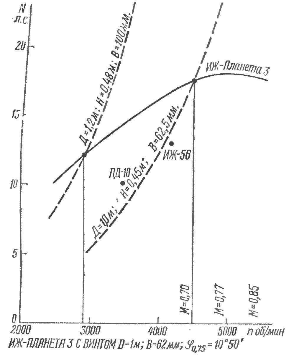
Fig. 7. External and throttle characteristics of the engine “IZH-Planeta-3 screw, D=1 m, H = 62.5 mm, 0.75 mm S = 10°50′.
You can ask speed, power, diameter and to determine the relative width of the blade and the corresponding step. The first method-defined parameters of the rotor 2, the second parameters of the rotor 1.
Example. To determine the geometric dimensions of the screws when the following initial data: shaft power screw 17,5 HP, shaft speed engine 4500 rpm, diameter of screw No. 1 1 m, screw No. 2 — 2 m. In figure 4, we define: Ø 1m = 12,5% (62.5 mm); h = 0,45 (N = 0.45 m) for Ø2 m=10% (100 mm); h = 0,40 (H=0.8 m). Screw No. 2 is taken the minimum allowable width is 10%.
Knowing the pitch determined by the angles of the cross sections of the blade. For this purpose, we find a value 2.5 times lower pitch:
Ø 1 m : H/2π=450/6,28=72 mm;
Ø 2 m : H/2π=800/6,28=127 mm.
From the diagram in figure 5 shows the construction of the angles of the cross sections of the blade.
Screw number 2 on the permissible circumferential speed determined by the maximum rotation frequency that is equal to 2250 rpm, which corresponds to the minimum reduction ratio. But at this frequency the width of the blade would be about 4%. From conditions of strength the width of the blade less than 10% can not be applied. Then according to the schedule (Fig. 4) define for 02 m = 10% and 17.5 HP, rotational speed of the screw shaft 1530 rpm Gear ratio downshift when it should be: 4500 : 1520=2,95.
Figure 6 shows the geometrical dimensions of the blade two-bladed propeller in percentage of the radius when the width of the blade is 16.5%. For our example, the width of the blade equal to 12.5 % and 10%. Therefore, all sizes of sections will be:
12,5/16,5≈0,755 for screw No. 1
and 10/16,5≈0,605 screw No. 2
from the dimensions on the drawing.
If according to the schedule (Fig. 4) defined by the width of the blade more than 16.5%, or it is possible to proportionally increase all dimensions by a twin screw to the required value, or to increase the number of blades so that the total width of them is related to the diameter, was found in the relative width.
Figure 7 shows the characteristic of the engine “IZH-Planeta-3 and the throttle characteristic with one of the screws. When installing on this engine two-bladed propeller without a gearbox with Ø1,2 m in increments of 0.48 m and a blade width B = 100 mm (dashed curve) the engine could develop only 2900 rpm and a capacity of 12 L. S. Thrust screw in this case would have amounted to 40 kg instead of 54 kg of rotor 1, properly sized to the engine. A thorough definition of the width of blades and angles of the sections, which allows you to use the full power of the engine and to the thrust close to the maximum possible.
VOROBYOV, G. MAKHOTKIN, engineers
Recommend to read
 VARTULI: A NEW GENERATION?
In the competition of young avtomodelistov as the winter sports season and summer now dominates the aviation scheme snowmobiles and cars. Their scheme is already thoroughly known and,... ABOUT VANT-POTENSAC AGAIN
In the manufacture of sailboats on a small scale a lot of work goes into the production of the most likely guys-putenkov. A method of simplified simulate these parts and nosing integral...
