
 In many cities on the lively streets and highways have electronic thermometers. Some of them, with light of a mercury column, like an ordinary thermometer, the other made in the form of a digital display. To make such devices themselves is not available to everyone. But the simplified design of the indicator can be manufactured by the forces of the circle of automation students.
The block diagram of the electrified thermometer — figure 1. Temperature sensor DT is hermometer resistance, placed in a protective casing and is included in one arm of an electronic self-balancing bridge EM. One of the main components of the measuring device — an analog-to-discrete Converter of ADP, which is made on the reed. They are located on disk, combined with the scale of the instrument. With temperature changes the resistance of the sensor, causing the imbalance of the bridge measuring circuit and the movement of the instrument pointer. Mounted it on a magnet causes the sequential circuit of the reed switches falling within its magnetic field.
The inclusion of lamps in the light display ST “runs” associated with analog-to-discrete Converter of the control unit cu. The sign of the temperature measured (“+” or “—”) highlight two lamps. His choice shall block the formation of the BFZ sign.
Consider the operation of the circuit of thermometer designed for measuring temperatures from -35 to +35°. Disk analog-to-digital Converter 70 radially placed reed switches, combined with the scale graduation e-bridge.
The reed switches corresponding to the same numeric values of the temperature (S1 and S2 for -1° and + 1°, S3 and S4 — 2° and + 2°, etc.) are connected in parallel (Fig. 2).
Each pair connected in series with the winding of one of relays K1 — K35 and parallel to their contacts K2.1 — K35.1. Contact plates K1.2—K35.2 commute the Indicator lamp H2—Н36. Lamp H1 included constantly.
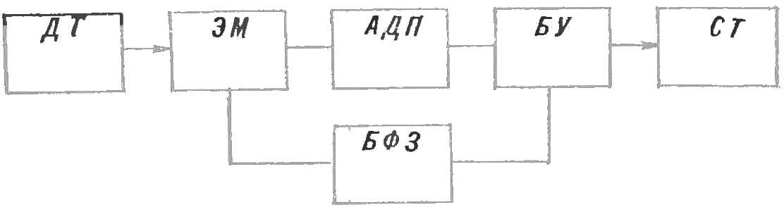
Fig. 1. A block diagram of the electric thermometer.
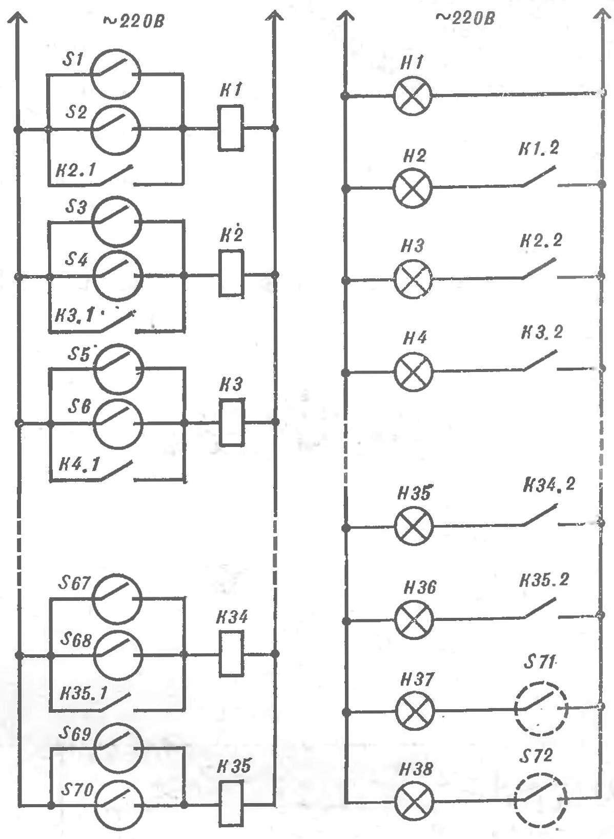
Fig. 2. Schematic diagram of the thermometer.
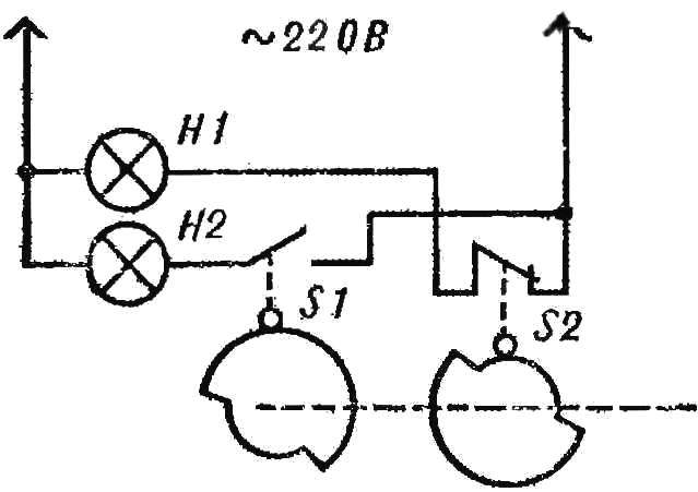
Fig. 3. Block diagram of the formation of the grain.
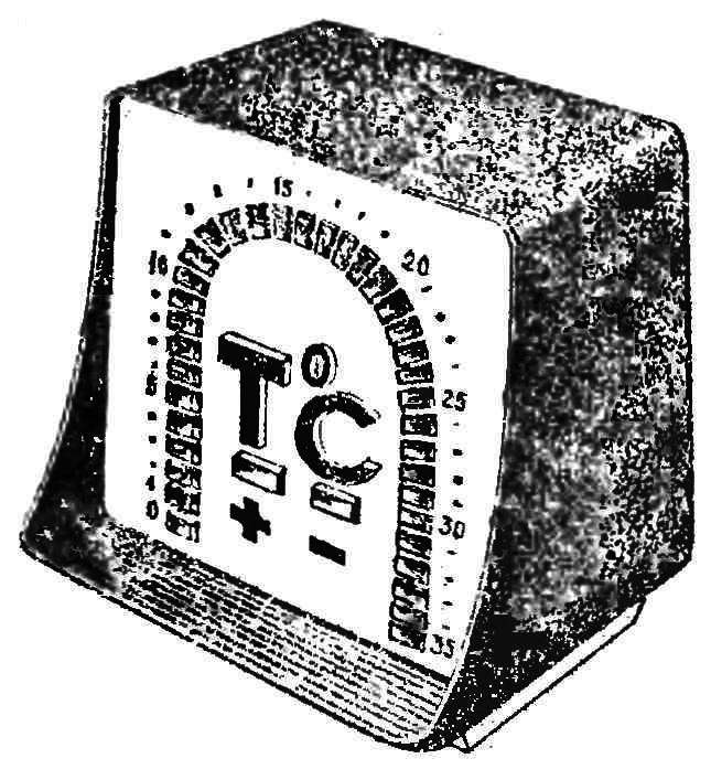
Fig. 4. The appearance of the temperature indicator.
The formation of the mark provides the positional device (Fig. 3) consisting of two profile disks, rigidly attached to the shaft of the reversible motor of the bridge, and two contacts S1, S2. Their condition depends on the position of the shaft motors and, therefore, the provisions of the niche of the instrument pointer. The shape and position of the profile disk is chosen so that when the temperature changes from -35 to -1 and° was closed contact S1 and if it changes in the range + 1— +35°—S2.
Appearance backlit display — figure 4. On front panel there are signal lamps with fittings to form a thermometer 0-35°. Two lamps in the center are used for indicating the sign of the temperature.
The permanent magnet should be of such shape and dimensions so that when you move the arrow worked reliably bridge two adjacent reed switch.
The temperature sensor is a copper resistance thermometer TSM, an automated bridge with a stationary electric device and 4805. Reed switches may be of any type. In the control unit is applied to the electromagnetic relay of mku-48, but if desired they can be replaced by thyristor keys. Dimensions of the scoreboard determines the size of the lamps. In our design, for example, lamps SL, and the fittings AC-220.
The scheme of the indicator, as a rule, does not require adjustment.
K. RAZUMOVSKY, Ph. D., A. NELGA, Dneprodzerzhinsk
Recommend to read
 SIBERIAN WAGON
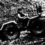
Offer readers acquainted with the original design of universal self-propelled tools, built by my brother Alexander. As he says (jokingly, of course), the idea of such a machine came to...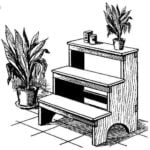 LADDER? NO, THE BOOKCASE!
The flower there is one "scary" term monsters. The so-called large plants, able to compete with the growth of the person. With the improvement of living conditions among fans of...
