
 “Dear edition! In rooms 11 and 12 your magazine from 1973 published a description of the guitar in Leningrad designers and lovers Guzina O. and D. Med, hex. The tool we liked.
We started to build this guitar. However, any guitar, as part of complex guitar — pickup — amplifier will not create a musical sound without low-frequency amplifier. Would like to see in the pages of “M-K” was described amplifier circuit bass and acoustic unit”.
V. Trotsenko, V. Galenko, A. Malyshev, Severodonetsk
Fulfilling the request of our readers, we publish a description of a powerful bass amp with an acoustic unit. Now the guitar will sound, as they say, in full voice.
The amplifier is designed for connection of electric guitar and microphone, but can also be used in conjunction with the turntable, tape deck, or radio.
Schematic diagram of the amplifier shown in figure 1. The first three stages (T1, T2, T3) collected in the circuit with common emitter. As transistors T1—T3 can be applied to any low noise transistors with a low value of reverse collector current Ік0. Resistors R1, R2; R10, Rll; R14, R15 form the basic circuits voltage dividers. In combination with the resistors R4, R13, R17, they provide the stabilization of cascades of preliminary amplification.
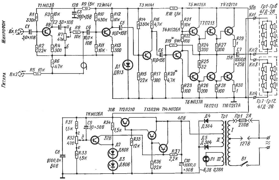
Fig. 1. Schematic diagram of amplifier:
resistors R24—R28 — MLT-0,5, К29, R30 — wire; variable resistors R7, R32—SP-1; the remaining resistors — VS-0,125 or MLT 0,25, electrolytic condensers — K50-6.
Since the design of the electric guitar has its own tone, the amp tone control is missing. If desired, it can easily enter in the amplifier by analogy with the known schemes. The overall adjustment level is accomplished by potentiometer R7, is included in the base circuit of the transistor T2.
The power amplifier (T4—T10) is made by a transformerless circuit. Transistors T5 and T6, T7 and T8, T9 and T10 are selected in pairs similar Gain (β = 50-70).
The quality of the amplifier is largely determined by the boundary frequency of the power transistors.
The fourth stage transistor T4 is covered by the negative feedback current through resistor R23. The cascade at the same time provides stabilization of the voltage at the middle point of the power amplifier.
Panoinverse cascade is performed on the transistor T5. T0 different types of conductivity.
The output stage is assembled on a two-stroke parallel scheme on a powerful transistors T9, T10. The choice of transistors for the amp is determined by the required output power of the amplifier.
The amplifier are AC tone voltage 127V or 220V. The rectifier is assembled by the full-wave circuit the diodes D4 and D5. To avoid fluctuations of the supply voltage between the rectifier and the amplifier circuit is included a stabilizing device is assembled on the transistors T11—T14 in the usual way.
The value of the stabilized voltage can be adjusted within certain limits by the potentiometer R32.
To improve the decoupling between the advanced and terminal stages of amplification in the power circuit an additional voltage regulator consisting of resistor R18 and Zener diode D1.
The modes of the transistors are indicated on the schematic diagram.
The power transformer TR1, electrolytic capacitors C7, C8, C10, circuit Board and power transistors T9, T10, T12 ka established the basis of the U-shaped chassis constructed from strips of sheet duralumin with a thickness of 2-3 mm. the Vertical bar (330X90 mm) and base (330X230 mm) bonded together using a 12-mm aluminum triangles.
On the front vertical panel mounted volume control, the lantern signal lamp, input jacks and a rocker switch on the network. On the back output jacks and switch the mains voltage.
The core of the power transformer recruited from УШ20 plates, thickness 50 mm.
The primary winding has 880 turns of wire of PEB-2 at 0.51; five hundredth revolution made the withdrawal for inclusion in the network with a voltage of 127V. The secondary winding comprises 2X85 turns of wire PEV-2 of 0.85, and the third 20 turns of wire PEV-2 of 0.35. It nourishes your pilot light.
The printed circuit Board (Fig. 2) designed for installation of small resistors all-0,125 or MLT-0,25 and electrolytic capacitors K50-6.
Radiators for transistors T9 and T10 is made from aluminium plates of size 120X70X5 mm, and for the T12 — size 160X70X5 mm. And the latter to give a compact G-shaped. To the chassis, heat sinks are mounted using textolite gaskets to prevent electrical contact between the housings of the transistors themselves.
Chassis with all nodes placed in housing size 340X240x100 mm. Vertical chassis panel, covered with false panels made of aluminum with a thickness of 1 mm, are the front and rear walls of the housing. The side walls are riveted two aluminum sheets. The surface of the housing and the false panels painted with nitro.
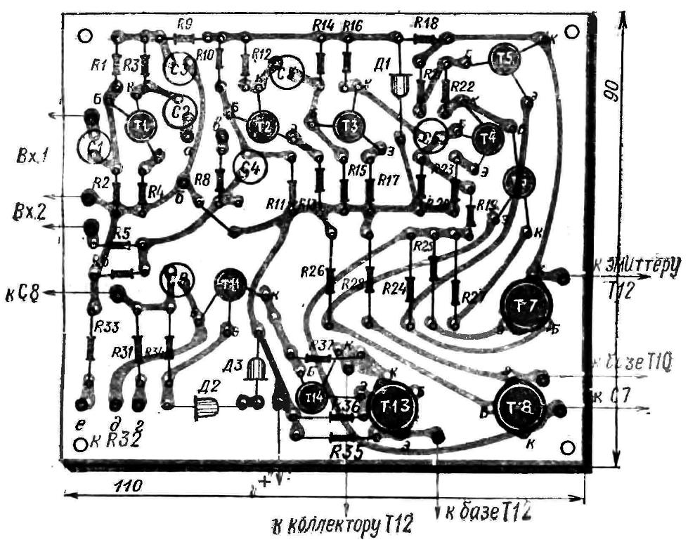
Fig. 2. The printed circuit Board.
Acoustic unit consists of two columns, each with six speakers 4GD-28. The total capacity is 45-50 watts. Column size mm 700X500X150 made from plywood 10 mm thick. the Side walls connect to the spike on kazeinovom to glue. The front wall is covered with decorative cloth, back — cut of hardboard with a thickness of 5 mm.
In this drill 30-40 holes Ø 5-8 mm. Inside column covered with layer of foam with a thickness of 15-20 mm, outside decorative film “under the tree”.
During installation of acoustic units have them properly spaserovat, that is, when series connection of the end of the voice coil of one Speaker to connect with the beginning of the other voice coil, etc., and in parallel — the beginning of one coil with the beginning of another coil.
Correctly assembled amplifier does not require complicated set up with radio equipment. Good results can be obtained using tester Ц52 or another like him. Connecting the speaker to the amplifier output, measure the quiescent current, i.e. current which is consumed by the amplifier when no input signal. If the transistors are properly matched, the quiescent current of the whole amplifier must not exceed 170 mA. The smallest value of the quiescent current and voltage of 15V at the collector of transistor T10 is established by means of resistors R19 and R20. replacing their preset variable resistors. Measuring accurate value of R19 and R20, in their place soldered fixed resistors. Performance of cascades of preliminary check of the voltage at the terminals of the transistors. The values are shown on the concept.
Amplifier output power can be increased by substituting transistors for the transistors П217А П210. Load resistance in this case is reduced to 2.5 to 3 Ohms.
M. CAPLIN
Recommend to read
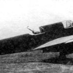 TRAINING AIRCRAFT UT-3
The starting point on the way to the first combat aircraft of OKB-115 was training bomber UT-3 (air-17, No. 17) - the first car with weapons created specifically for the military. ... THE TECHNICAL PEN FROM THE “BALL”
One time I urgently needed to draw a charge, and at hand, no needle to scratch or ruling pen, although the lacquer was. Then decided to fill them inscribed with the rod of a ballpoint...
