
 Aquarists usually determine the turbidity of the water in the aquarium, visual manner (“eye”), and beginners don’t change it until then, until it is radiating the smell. However, with the help of an electronic device, which is easy to collect a couple of free evenings, you can control the suitability of water in the tank for future use, with high precision, eliminating the notorious “human factor”. Will benefit from this approach all people and their Pets in the aquarium.
Electronic device control the transparency of the liquid based on the principle of changes in the characteristics of the light flux as it passes through the liquid. Turbidity occurs due to the formation of various insoluble organic particulate (colloidal) minerals.
The turbidity of the solution measured photometric (hence the name of the device — see below) way, comparing the intensity of the noise it the light with this index obviously transparent (standard) solution. Prototypes of the sensor are industrial devices — photocalorimetry (e.g. KLF-2 and KLF-3), designed to measure light transmittance and optical density of the solutions.
However, these industrial devices are either difficult to implement and configure (they require special instrumentation) or of little use at home. Therefore, to solve specific tasks(determining the degree of transparency of the water in the aquarium) was developed photocolorimeter, the principle of which is based on the conversion of luminous flux into an electrical voltage.
The transmission factor Z is determined by the formula
Z – (U – Ut)/(U0 – Ut) x 100%, where U is the output voltage in the study of the solution,
U0 is the output voltage in the study of distilled water,
Ut is the output voltage when the dimming of the photosensitive sensor, which is characterized by a tempo current. According to the passport data for FD-24K, applied as a photosensor, it is 2.5 µa.
The same current must be in the circuit R1V1. A complete blackout of the photodiode VD1 comprises applying on the photosensitive surface of black PVC electrical tape. It is this experiment that I conducted when creating the device, confirmed the passport data of the photodiode FD-24K. Accordingly, the output voltage of the device current is directly proportional to VD1.
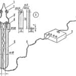
Functional diagram of the device shown in figure 1.
Electrical characteristics of photodiode FD-24K. Field of the spectral sensitivity of 0.47 and 0.12 µm. Wavelength of maximum spectral sensitivity is 0.75 0.85 µm. The maximum operating voltage of 27 V. the Dark current is 2.5 µa. Resistance “case — finding” of the photodiode is at least 100 Megohms. The maximum operating illuminance of 1100 Lux.
Electrical characteristics of photodiode FD-24K was allowed to include it in the circuit with operational amplifier (op amp), General purpose high input impedance. At the entrance of the shelter КР140УД1208 implemented differential cascade with the matched pair of field-effect transistors. The amplifier on the chip КР140УД1208 selected for the device due to its optimal electrical characteristics (resistance load on the output OU Rh > 2 kω and high sensitivity input).
Consider the circuitry of photocolorimetry presented in figure 2. Operational amplifier DA1 is a DC amplifier, the input of which is connected photodiode VD1, which is open in the diagram mode of the oscillator, converting the energy output into electrical energy (photo-EMF) a Photodiode connected to the inverting input of op-amp (pin 2 DA1) as the generator OU converts current into voltage at the output (pin 6 DA1) Output OU is loaded on the portable digital voltmeter PV1 of the M-830-V, indicating that the voltage value, dependent on transparency (turbidity) of water.
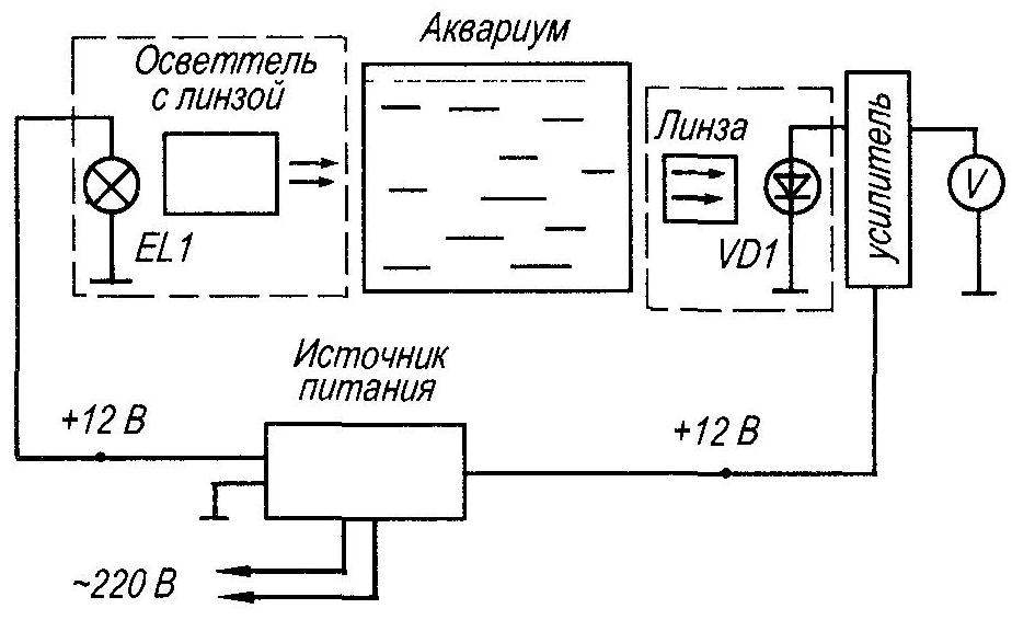
Fig. 1. Functional diagram of the device for determining the transparency of water in the aquarium
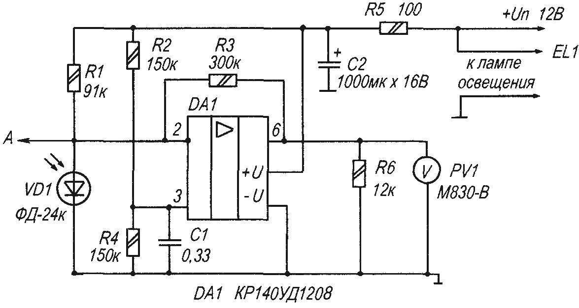
Fig. 2. Schematic diagram of photocolorimetry
Resistor R6 shunts the voltmeter PV1 to protect the OPAMP in case of an open contact with this device (when you turn off the voltmeter). Output op-amp the maximum voltage of 10 V will be at the maximum photocurrent of the photodiode VD1, that is, when projecting the luminous flux from the led lamp (or bulb) through the cuvette with pure distilled water.
The photo shows the current setting for testing the transparency of a 3% salt solution. In this experiment, the voltmeter made up of 8.91 B. This is very close to perfect transparency of the liquid. Thus, the maximum instrument reading РV1 included in the measurement mode of voltage (about 10 V) corresponds to pure water. And minimal, respectively, solution of defined turbidity Recording voltmeter is carried out empirically for different values of transmittance, which are fixed at different turbidity of the water in the aquarium, the same light time.
Luminous flux in this case comes from led bulbs, which are already equipped with lens Lamp lighting device photocolorimetry fixed vise and the clamp on one level, It is important for measurement accuracy Similar to examine the turbidity of the water in the aquarium.
The establishment
The establishment is the installation of the device “zero”, that is, to the maximum voltmeter РV1 in the study deliberately transparent solution of distilled water, placed in 3-liter jar (or other suitable cell) with a volume of 0.5 L. 3 This adjustment is performed by selection of the resistor R1.
All fixed resistors type MLT-0,25 Mr-125. The oxide capacitor C2 smooths the ripple of the power supply. Instead of the voltmeter М830-you can apply any voltmeter (preferably digital) with a limit of measurement of DC voltage of 10-20 V.
The mounting parts of the device
Led lamp ЕL1 is fixed in the housing of the portable lamp with a reflector, and the lamp rigidly mounted in a miniature vise (clamps) in front of the photo sensor the photo sensor is fixed in a Vice on the other side of the aquarium (the cuvette with the solution) in any suitable compact housing with lens Housing photo sensor installed next to the light source, aligning the horizontal plane of the ruler or the building level.
Alternative photocalorimetry
In addition to readings with a voltmeter РV1, you can use other means of parametric alarm once a light or sound indication that will expand the capabilities of the device. It’s easy to implement, bringing simple circuit of the image sensor presented in figure 3.
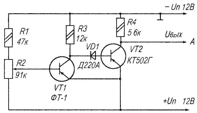
Fig. 3. A schematic circuit diagram of the photo sensor transistors
Phototransistor VT1 in this circuit is a photo sensor receiving the light signal to the output And connect any device sound or light alarm with the correct polarity connection, for example a cap with built-in AF generator type KPI-4332. If excessive turbidity of the solution monitored the audible output level. The threshold device is now set by adjusting the input voltage divider or the first amplifier of the cascade of the parametric indicator.
After this customization is not necessary in carrying out regular physical-chemical experiments, and turbidity in excess of the established threshold will cause an immediate alarm (e.g., audio that the owners will hear even in the kitchen).
The principle of operation of the device
Luminous flux from the led lamp is parallel to the window of phototransistor VT1. The adjusting device is a variable resistor R2. At the bottom (under the scheme) the position of the slider of the variable resistor R2, the sensitivity of the device is minimal.
In absolutely pure water the phototransistor VТ 1 is fully open (the resistance of the emitter — collector minimum), respectively, the transistor VT2 (included in the scheme of the current amplifier) is locked. When the water in the aquarium becomes cloudy, the light flux coming to the working surface of the phototransistor VT1 from the led lamp through natural contaminated waste water will be proportionally reduced. Depending on the resistance at the midpoint of a voltage divider implemented with R1 and variable resistor R2, a phototransistor VT1 may be kept open, partially open or closed. Accordingly, the transistor VT2 is in the locked, partially locked or open. Thus, when the turbidity of water natural sediments luminous flux to the phototransistor VT1 is reduced, it gradually closes through the resistor R3 and the diode VD1, the current supplied to the base of transistor VT2, the last partially reopened (because water, even muddy, can not transmit light), and between point a and ground, there is a difference of potentials (the more, the more turbid the water in the aquarium).
Installation for testing the transparency of a 3% salt solution
To A point in the circuit can connect the device signal amplification by operational amplifier, or other device status indication. For example, the parametric signal, or (when greater accuracy of measurement) unit of the ADC, or milliammeter All of them are connected with the correct polarity in parallel to the constant resistor R4.
Details
Instead of the phototransistor FT-1 is allowed to use its foreign counterpart OSR-70 without any alteration of the scheme. If this is not unique, why not make the phototransistor itself neatly sawed off the hat of an ordinary semiconductor type transistor МП39-МП42 (or similar). Or for example, replace VT1 photodiode FD-7 (or equivalent), including it in accordance with the polarity (cathode to “+” IP) instead of a transition “emitter—collector” of the transistor VT1. Instead of the limiting resistor RZ include a voltage divider R1R2.
A. KASHKAROV
Recommend to read
 HOT PENCIL
Small red-hot spiral, fed by electric current, in skilled hands becomes a kind of pencil, which is burned on the tree. This elektrovyzhigatel. For its production you will need a... BALCONY DRYER
To quickly dry the washed linen, the hostess usually hung out on the balcony: comfortable but not very aesthetically pleasing. However, drying underwear will not be visible from the...
