
 In the age of microelectronics, computerization and display multimeters gauges perceived by some almost as an anachronism. However, life proves the fallacy of such views.
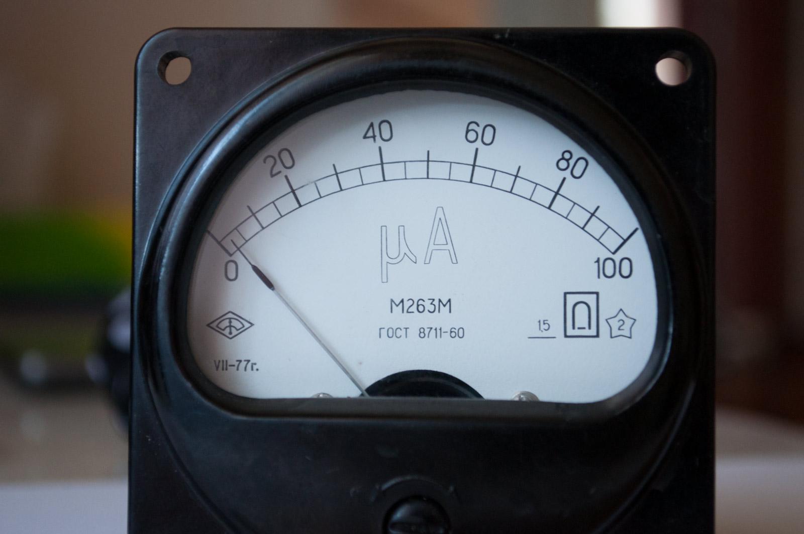
We offer homemade device is another proof. Having “output” switches multi-range indicator coil system with full deflection 100 µa, it is quite compact and allows with sufficient accuracy to measure the constant and variable voltages and currents, resistance, capacitance, inductance, temperature, to check the efficiency of the quartz resonators, and to assess their quality, to choose diodes with the same parameters
The basis of the universal device electro-and radio engineering is a millivolt DC and AC (frequency range from 20 Hz to 5 MHz!) voltage limit of 100 mV. Circuit design is such that in the measurement of various parameters is used… the same divider R1 — R9 (Fig.1). Very comfortable and decimal frequency ranges: 0.1 V, 1 V, 10 V, 100 V, 1000 V (for the measurement of static and alternating stresses), and 1 µa, 10 µa, 100 µa, 1 mA, 10 mA, 100 mA, 1 A (for currents). Since the voltage divider has the frequency of compensation, when measuring large U, the bandwidth is narrowed.
Resistance measuring device has the following ranges: 10 Ohm, 100 Ohm, 1 kOhm, 10 kOhm, 100 kOhm. 1 MOhm. And that when operating on sub-band 1 MW to do without the use of additional (dokazatelstvo) resistor resistance of 100 Mω. used to reduce the feeding voltage to 1 V.
When measuring inductance tokisada resistors is available (the built-in generator DA3) AC voltage (an effective value of 1 V, frequency of 159 Hz). “Non-standard” frequency is provided by the desired proportionality factor between the voltage dealt with by the millivoltmeter, and inductance (2nF for this frequency is taken as 1000). The sub-ranges of measurement of inductance: 1 mH, 10 mH, 100 mH, 1 GN 10 GN 100 GN.
When measuring capacitance, on the test capacitor voltage is 1 V. it Comes from the same generator DA3.
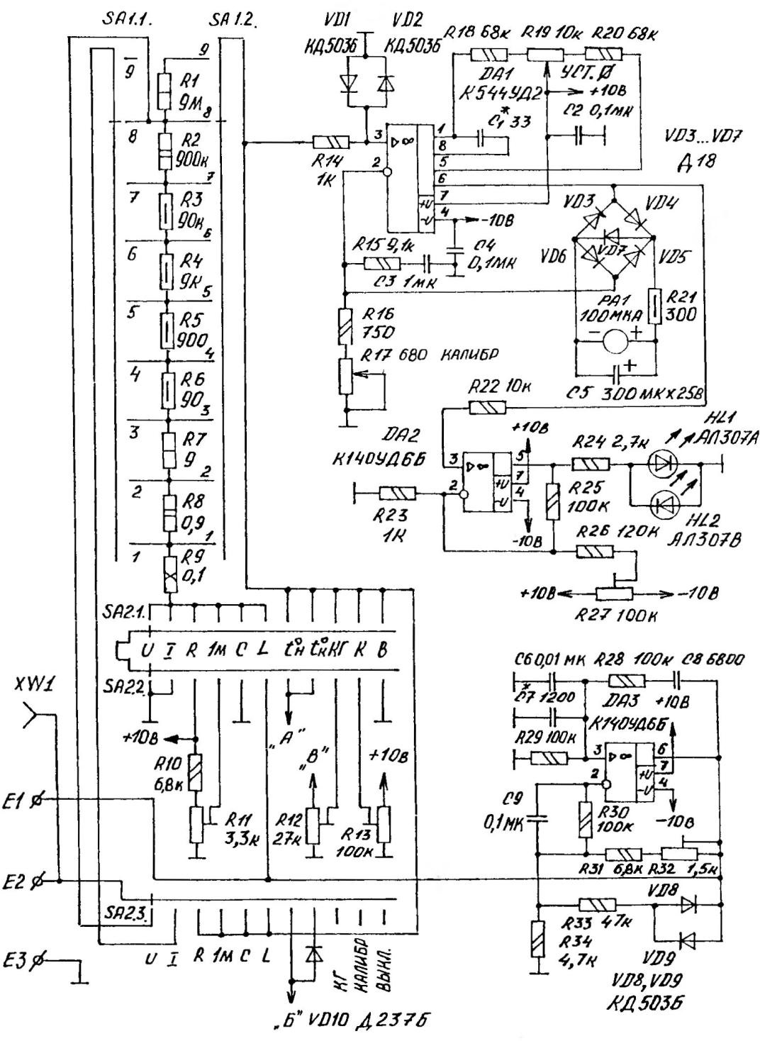
Fig.1. A circuit diagram of the basic part of the device
The voltage taken from a relatively low resistance resistor connected in series with the capacitor will be proportional to the capacity of the latter. The sub-band measurements are as follows: 100 pF, 1000 pF to 0.01 UF, 0.1 UF, 1 UF, 10 UF.
The temperature of the device determines the accuracy of the two range from 0 to +100 °C and 0 to — 100 °C. the range of values (“+” or “-“) induced by contrasting LEDs (e.g. red and green) colors.
When working at high frequencies (up to 15 MHz) the device can be used as an indicator of the AC voltage.
The main input terminals of the universal unit — E2, and EZ. To simplify switching test capacitor connected to E1 and E2. Coaxial connector XW1 is used in the measurement of constant and variable stresses. Operation mode select switch SA2, and the limits of measurement — SA1.
Milliammeter DC voltage is collected at the operational amplifier DA1. The diodes VD1 and VD2, and resistor R14 to protect it from overloads on the input. The limit of measurement depends on the current full deflection of the arrow PA1 and resistors R16, R17, R21. As an indicator applied to a microammeter with a measuring limit of 100 mA and the resistance of frame 700 Ohms.
The device can be applied to a microammeter of 100 µa with a different resistance, but in this case the value of the resistor R21 should be changed so that the total resistance RA1 and R21 was 1 com. It is necessary to obtain the passport of the load circuits DA1 (2 ohms). The total load for the circuits consists of resistors series-connected resistors R16, R17, R21 and the resistance of frame PA1.
The handle of the resistor R17 is displayed on the front panel. By the calibration of the device But the balance (zero) the DC current is carried out by resistor R19. Control knob the latter is also displayed on the front panel.
Resistors R18 and R20 serve to limit the boundaries of the balancing DC current. Chain R15СЗ adjust readings of millivoltmeter for measuring the effective value of the measured variable components.
The diode bridge VD3—VD6 allows you to measure both AC and DC voltage of any polarity without any switching. Diode VD7 is used to limit the peak voltage that occurs when switching the measurement range, and in conjunction with resistor R21 and capacitor C5 for damping (quieting) of the prevent breakage the base of the indicator PA1. This is important as the sudden movement arrows threaten to occur not only in the translation of the device in the modes of measurement of resistance and inductance (when the input probes open), but when switching the measurement range.
The polarity of the DC voltage (and the sign of the temperature) performed on the operational amplifier DA2. Indicate the polarity of the two LEDs: one green light (negative polarity or temperature), and the other is red (“positive” value of the investigated parameter). When measuring AC voltage and current burn both HL1 and HL2. To achieve balance in the configuration of the indicator serves as a trimming resistor R27.
On the chip DA3 completed 159-Hertz generator. The desired level of output voltage is stabilized by the diodes VD8 and VD9, included counter-parallel. To set the desired output voltage is provided a trimming resistor R32, and to determine the health of the quartz resonators (frequency range from 0.5 MHz to 30 MHz) is a generator schematic diagram is shown in figure 2A.
Actually, the generator is assembled on the transistor VT1, and the VT2 transistor emitter-follower is made. The role of the diode VD11 is to be a kind of voltage limiter at the output of the device. The required form of the signal sine wave.
Remove the “In” voltage goes to the input of the millivoltmeter. Socket XW2 provide for the removal of the output signal of the generator and feeding it into a frequency counter or oscilloscope.
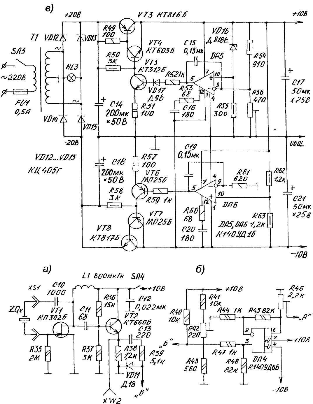
Fig. 2. The schematic of the generator (a), unit of measure temperature (b) and the source of bipolar power supply (in)
The site of temperature measurement (Fig.2B) is assembled at the operational amplifier DA4. Outer teplomarket — silicon diode, anode connected to terminal E2 and the cathode to DRIVE when the position of the switch SA2 (see Fig.1) in position t°H. For temperature measurement (the position of the SA2 — t°K) as the sensor uses diode VD10 (terminals E2 and E3, it should be shorted). The lower limit of measurement (0 °C) set trimming resistor R42, and the upper (100 °C) resistor R46.
Use the above site and for the selection of diodes with the same parameters. Check the instances connected alternately to terminals E2 (anode) and EZ (cathode). Diodes with the same parameters will give the same temperature reading. However, note that the accuracy of selection is higher if you use probes with an insulating coating (plastic) to prevent warm-up check the diodes warm own hands.
Powered universal device from the embedded bipolar regulated supply that consists (Fig.2B) of the power transformer T1, diode bridge VD12 — VD15 and two stabilizers (+10 V and — 10V). The latter are regulated by the trimmer resistor R56. If you change the Colour of one polarity (e.g., +10 V) will occur automatically track level and the corresponding adjustment of the supply voltage of the other polarity (-10). The factor of stabilization of both stabilizers is not less than 20 000.
The device uses a common radio. The power transformer should be designed for a capacity of at least 10 watts. He has two secondary windings, outstanding for 16 V. operating voltage light bulbs HL3 27-35 IN
In the selection of other electronic components is permissible and replace. So, instead of КТ816Б transistor (VT3), you can use КТ815 and its analogues. As VT8 acceptable КТ817Б, КТ815. All semiconductor triode model КТ603Б here on КТ608, diodes D18 — D20, KD503 — KD522, and Д237Б on any silicon counterparts in a metal case. Resistors R1—R9, precision, type PLMN-1, PLMN is 0.5. Each of the “mnogoletnih” resistors composed of two less powerful (resistance of twice that indicated in the diagrams) are connected in parallel.
V. RUBTSOV, Astana, Kazakhstan
(To be continued)
Recommend to read
 WINDSURFER ON LAND
Historians say that the sail appeared on land about four thousand years ago! Fiction? No, the reality is — there is documentary evidence. In 1935 the Italian archaeological... CUTTER OF HOOP
Loves to embroider or cross stitch is used for the tensioning of the fabric an ingenious device — the Hoop: two wooden or plastic rings, one of which together with the tissue fits snugly...
