
 (The end. Start at # 1 ’03)
 To build the most part universal appliance electrical and radio technology used by printed circuit Board (Fig. 3) from foil fiberglass 1.5 mm thick. the Rest of the installation is mounted. Power transformer is separated by an iron partition thickness of 1 mm.
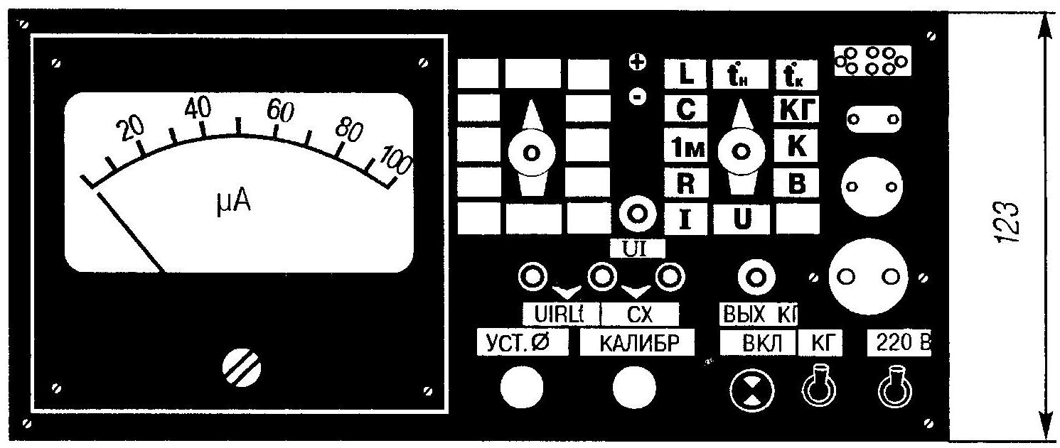
From 1 mm sheet aluminum made chassis, case and front wall of the device, and the last pair of nitro painted black. On the front wall displayed the controls and control nests under various types of quartz resonators and pasted “nameplates” — strips of paper with explanatory notes. On top of all this are covered with false panels of transparent organic glass.
Configure the instrument starts to test the power supply and adjust output voltage +10 V by trimming resistor R56. The voltage of the second stabilizer (DA6) should be set at the level of 10 V.
Then the instrument switches to the measuring mode voltages on any limit and by adjusting the resistor R19, the arrow PA1 set to zero. Then SA1 is transferred to the position corresponding to the limit of measurement 10 V. Feeding the input of the device and pre-calibrated DC 10-volt voltage, rotate the engine R17 CALIBER, ensuring that the arrow indicator has reached the maximum scale value (100 µa).
Translating SA1 in the position of the gauge and adjusting the resistor R13 again set the arrow of the device RA1 on maximum of the scale (100 µa). Pen R17 without touching. After completing the above steps handle R17 can be used as the voltage calibration of fixed resistor R13. In the future, when the instrument calibration can produce a resistor R17 in any position of the switch SA1.
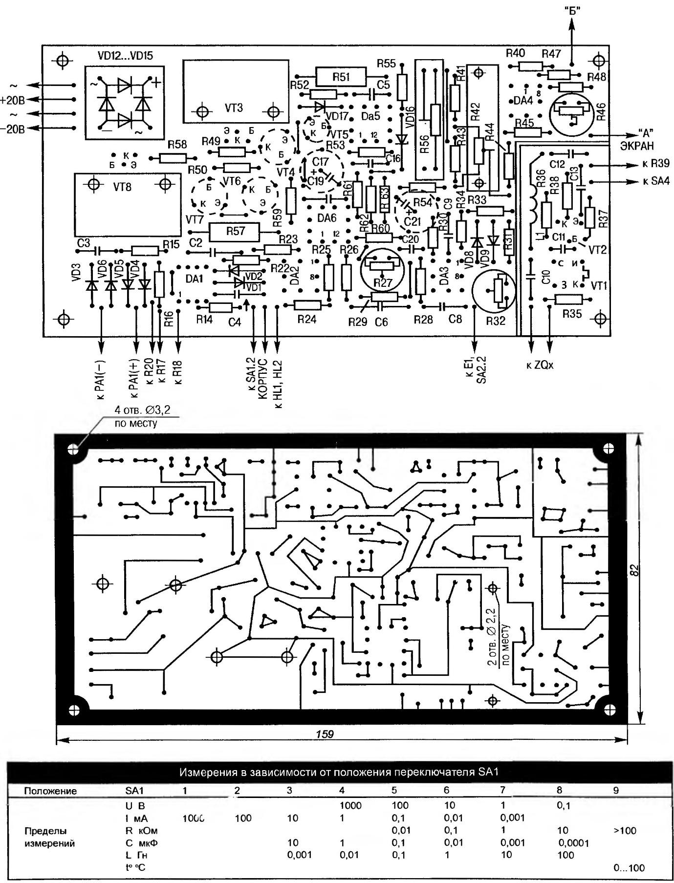
Fig. 3. A printed circuit Board from the parts and printed conductors
If any of the provisions of the switch SA1 is observed in excitation (testimony PA1 differ from zero in the absence of the input signal), it is necessary to increase the capacitance (50 pF). If the excitation of no in the absence of C1, the capacitor can not be set in the scheme. Pointer polarity (DA2) set the resistor R27 in the absence of the LEDs HL1 and HL2 with zero indications of the PA1.
Control of the correctness of the readings in the measurement mode of resistance lead by connecting to terminals E2 and EZ exemplary resistor, the reading from the scale and comparing them with the actual values of the resistance. When measuring resistance in range 1 MOhm (SA2 in position 1, SA1 — 9) by adjustment of the resistor R11 achieve compliance readings RA1 the resistance of the exemplary resistor.
Then proceed to configure AC voltage generator (DAЗ). The frequency of the generated signal 159 Hz set by selecting the values of capacitors C6 — C7 and rude — exactly. Output voltage 1 V (effective) put a resistor R32. Control is carried out according to the testimony of avometr in the measurement mode of the alternating voltage.
The accuracy of the capacitance measurement test by connecting a test (model) of the capacitor to the terminals E1 and E2 and collating its value with the data on the device RA1.
Control of the correctness of the readings in the measurement mode inductance are similar. Exemplary inductance connected to terminals E2 and EZ.
Work of the quartz oscillator (VT1) check the position of the KG switch SA2 (SA4 — enabled). Quartz controlled is connected to the socket XS1. Rotation of the resistor R12 achieve compliance the actual value of the alternator output voltage to the readout PA1.
To monitor the output voltage of the generator at a frequency controlled by quartz to 5 MHz is possible if to connect a coaxial cable socket XW1 and XW2. It is necessary to switch SA2 to set V I (measurement of stress), and SA1 in a different position, in which it is most convenient to read PA1.
Frequency of the generated voltage is determined by the frequency and the waveform monitor on the screen of the oscilloscope, connecting them serially to the nest XW2. The activity of quartz (hence, its q-factor) check the output voltage of the generator. What it is, the above control parameters.
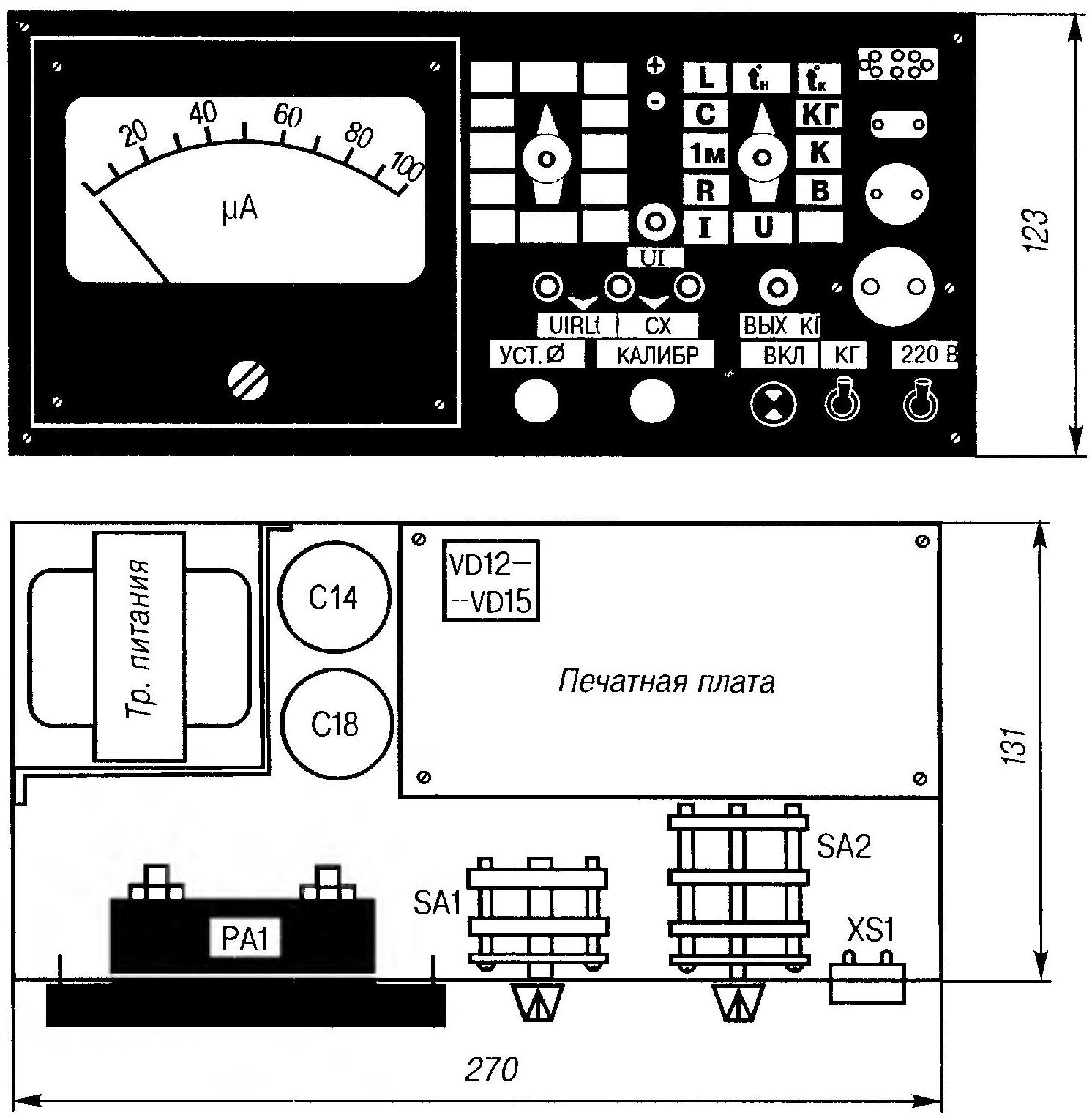
Fig. 4. Such a device will be able to make each (housing and the front wall is covered in black enamel, the false panels of Plexiglas conventionally not shown)
Debugging site of temperature measurement (DA4) are adjusting resistor R42 zero indications PA1 (0 °C). The temperature sensor is the metal part of the diode case (the glass cell) is lowered into the vessel with melting snow.
Then, lowering a temperature sensor into a vessel of boiling water, seek (tuning R46) arrow PA1 set at its maximum scale 100 mA, which would correspond to readings of +100 °C. After cooling sensor check the correctness of intermediate readings, controlling them at human body temperature (36,6 °C) or comparing the readings with the data from the exemplary thermometer when measuring the temperature of the environment.
Diode VD10 is used to control the temperature of indoor air, terminals E2 and EZ at the same time should be shorted, and as a remote temperature sensor is being used by another diode of the same type. Its anode is connected to terminal E2, and a cathode — EZ.
Named the diodes should be selected according to the same temperature readings. It is desirable to use the tweezer with heat-insulating coating so as not to heat the housing with fingers.
Similarly, you can pick up pairs with the same parameters for other types of diodes.
V. RUBTSOV, Astana, Kazakhstan
Recommend to read
 EQUIPMENT FOR A SWIMMER
A boat with a rower moves much faster than a swimming person, even with fins, although the drag force is three or even four times greater. The efficiency of oars is higher than that of... THE LAST CAR ENZO FERRARI
SNCO Ferrari, the famous racing driver and sports car designer, was born in 1898 in the Italian city of Modena. By the will of Providence was the same age as the car, Enzo already in...
