
 From Nickel-cadmium batteries with a life expectancy of 100-200 cycles of charge-discharge. Discharge below 1V per cell leads to a sharp reduction in the duration of battery life. How to control a threshold voltage of discharge of the battery during operation? To have with you the measuring device is inconvenient. It functions best to hold the indicator — sound generator with a silicon Zener diode. Its voltage stabilization determines a controlled level of discharge.
Schematic diagram of the audio indicator for the battery 7D-0,1 — figure 1. Based on his generator is an asymmetrical multivibrator transistors V1, V2 with different conductivity and the Zener diode V3. Load generator is a compact phone TM-2 or TM-2.
If the voltage controlled battery G1 exceeds the stabilization voltage of the voltage V3, the phone heard the distinctive sound. Otherwise, it needs to be recharged.
The indicator is assembled on the connection module power (Fig. 2). Circuit Board made of foil Micarta thickness of 1 mm. connector Terminals (for example, from the battery “Crown”) attached to it with rivets for extra washers-substrates with a thickness of 1 mm. On one side with terminals located and details of the generator.
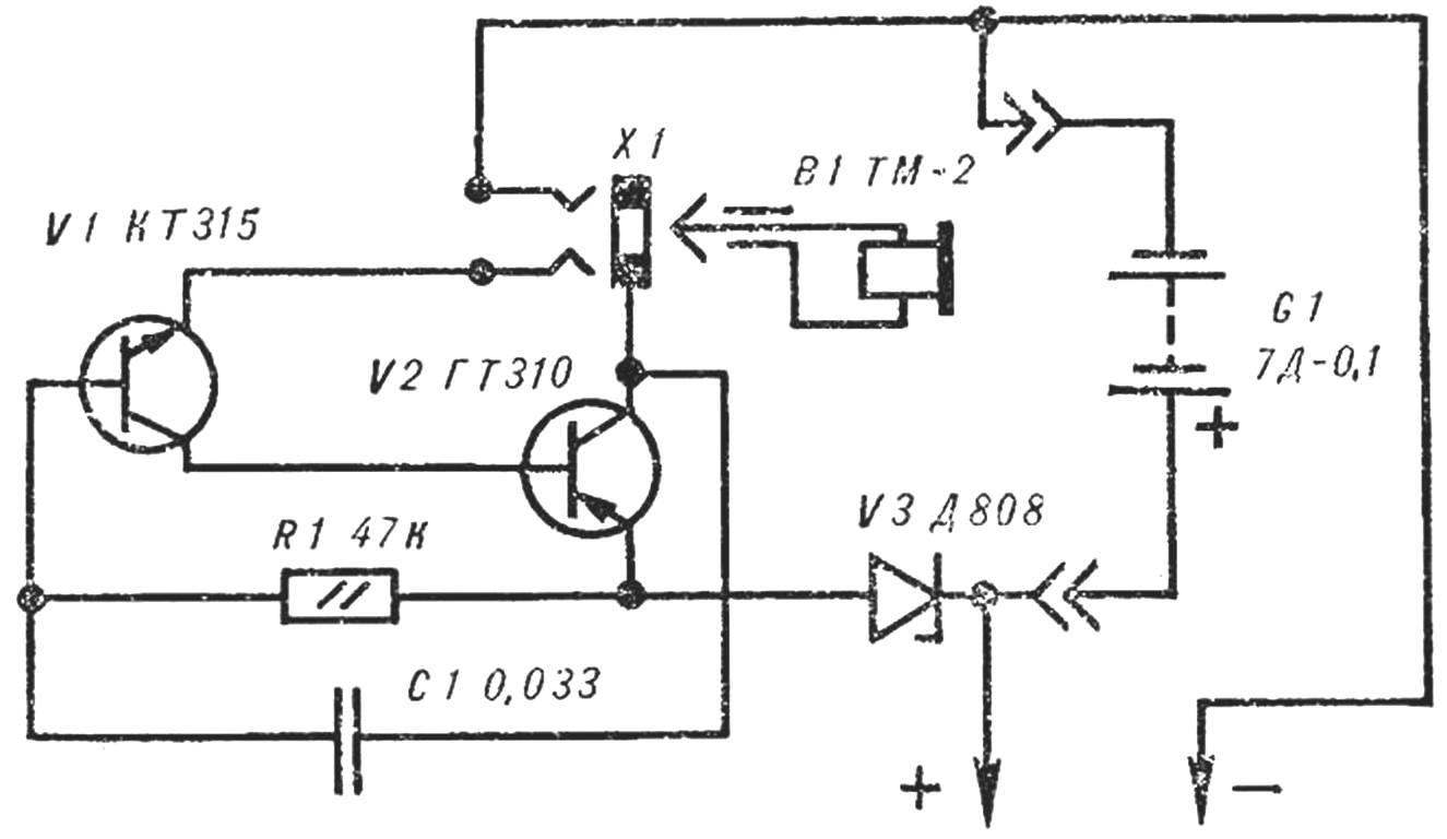
Fig. 1. Schematic diagram of the alarm device.
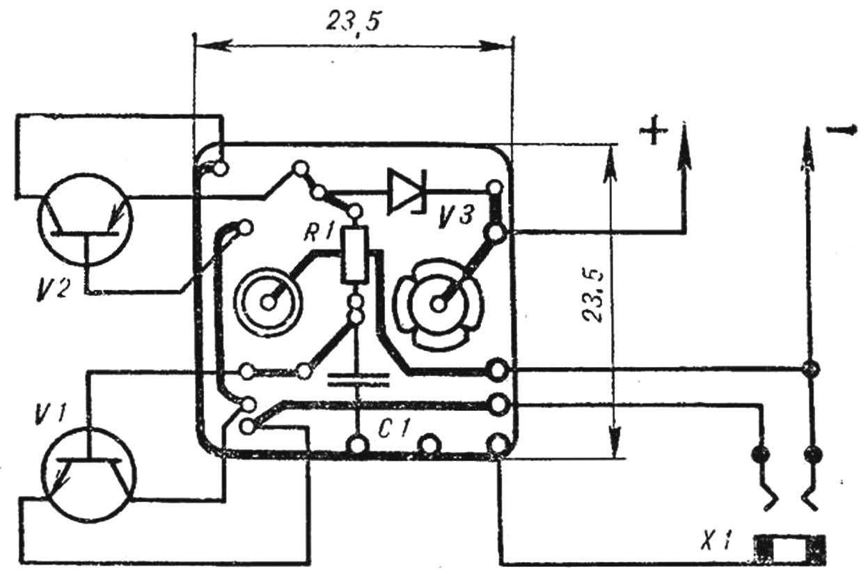
Fig. 2. Wiring diagram audio consoles.
Female socket X1 taken from the phone of TM-2M. After replacing the small spring-loaded contact big Jack it is recommended to install on the device that uses the battery.
Instead of the Zener diode Д808 with voltage stabilization of 7.1—7.3 In suitable Д814А. Resistor R1 — ULM-0,12, condenser S1—KLS.
I. BRAKES, Smolensk
Recommend to read
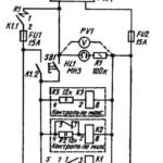 RELAY PROTECTION
Voltage instability in the regional power lines, unfortunately, are not so rare. Especially during strong winds, when the wires of overhead lines of 0.4 can overlap. Because of the...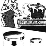 PLATE HOSTESS-CHISTYULI
Neat woman, always worried if the cooker escapes milk or zarazhayutsya fat burners from the naked red-hot pans. Moreover, the penetration is not so easy to clean. A small trick will save...
