 It is known that in the process of operation of car batteries is required from time to time to do preventive charge-discharge cycles to prevent sulfation of the plates and thereby increase their service life. There are lots of devices, including homemade (see the journal “modelist-Konstruktor” No. 9— 11 ’01), through which the battery is initially discharged to 10.5 V with a current of 1/20 of its capacity and then the voltage on the terminals is communicated during the charge-discharge cycle to 14.2 to 14.5 V. And the ratio of the charge-discharge current components are in the majority supported almost perfect — 10:1, and the pulse durations of the charge-discharge — as 3:1, but…
I (probably many other motorists, not to mention the professionals) are unable to meet the massive transformers and heatsinks krupnogabaritnogo inherent in the structures of these devices. It seems that miniaturization and other features of progress, violently manifested, say, in television and computer technology, almost veiled in the instrument that the domestic market provides a “modern discharge-charging, desulfurizers”.
Desperate to find a ready-made design with the parameters I need, he created his. Its main features are: the charge current is regulated by a variable resistor, the output on the front panel in the range from 2.5 to 7 A. Hence, the required charge-discharge component is 1:10 can easily be set for most of the battery operated. The discharge current is fixed equal to 2.5 A (determined by the electrical parameters of the lamp EL2). Well, the discharge current is in the mode of desulfuratsii is 0.65 A (depends on EL1 lamp).
Charge time is 17 s and the category — 5 s. That is, the ratio of pulse duration charge-discharge is approximately equivalent to the recommended 3:1. However, this setting can be changed by the selection of resistors R35 and, accordingly, R36. Power consumption depends on the charge current and is equal to about 30-90 watts. Adjusting the threshold of the Comparators is carried out with trimming resistors: R34 — lower limit (10.5 V) and R31 — upper limit (14.5 V). The device is powered by the battery and from household grid voltage of 180-250 V.
When switch SB2 is in position a CHARGE (see schematic diagram), control over the battery is missing, the category of impossible. In this mode, when enabled network SB1 unit works as a regular charger with adjustable charging current. With the installation of the switch SB2 to the mode DESULFATACE are alternately charging and discharging the battery.
When you click on the START button (SB3) is the initial discharge current 2.5 A voltage up to 10.5 V, and then charging desulfatohirudin way to a voltage of 14.2—14.5 V, then the device in MOMENTARY mode, is automatically disabled. If the push button switch SB4 is in the position many times, the process of the charge-discharge is repeated arbitrarily, which is a necessary condition for the “treatment” of the battery.
The “standard” power supply (220 V, 50 Hz) the device is carried out through the fuse FU1 and the filter L1C1C2 preventing against the penetration of interference in the network. Incoming AC voltage is rectified by a diode bridge VD1—VD4 diodes and smoothed by capacitors C4 and C5. The presence of resistor R2 is dictated by the need to limit the current during charging of the capacitors. The optocoupler VU1 is controlled by the presence of voltage in the network or when it is absent, a lock (for printin.9 logic element DD2.3) discharge mode of the battery.
Next. If you connect the battery, then the battery + 3 window comparator DA2 set the voltage high level (logical “unit”). Then opens the semiconductor triode VT6 and Shine the led HL1 Indyk. CHARGE. A low level (logic “zero”) appeared on the collector of this transistor will flow to the terminal 9 DD1.3 and 13 DD1.4 and will thereby provide unlocking low-frequency generator. Duty cycle will determine the value of resistor R36 (charge) and R35 (category) and frequency — nominal capacitance C18.
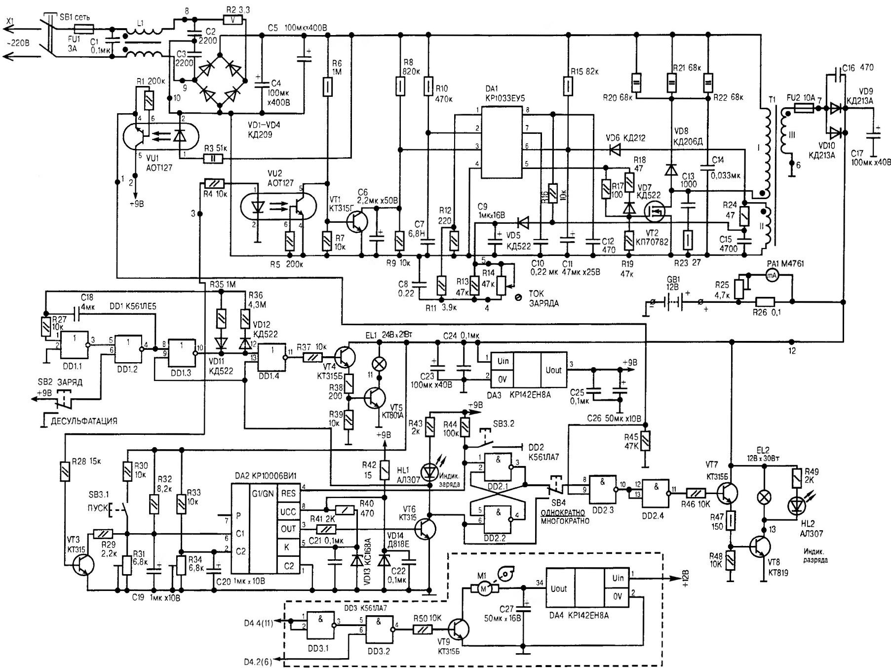
A circuit diagram of a pulse automatic Raspadskogo device
On printin.10 logic element DD1.3 during charging of the battery set log.1, blocking the transistor VT3 high threshold (14,2 In) of the comparator DA2. This algorithm is due to the fact that the comparison with the threshold named above should take place only in discharge mode to prevent triggering of the comparator nedoskazany battery. The same high level via optocoupler VU2 and the transistor VT1 starts the voltage Converter.
At the time of discharge appearing on the conclusions. 10 DD1.3 voltage logic low level. This creates favorable conditions for the Converter lock-up, as well as to establish the log.1 vyv.11 DD1.4. The result triggered the electronic key, assembled on the transistors VT4, VT5, and the discharge of the battery through an incandescent lamp EL1. Inflated the electrical parameters of the latter (24 V, 21 W) help to prevent premature burnout.
Click on the SB3 START button leads to the setting voltage of low logic level at the comparator output (vyv.3 DA2). The VT6 transistor is closed; it is a generator, assembled on IMS DD1, and an electronic voltage Converter; set log.1 vyv.3 RS-flip-flop, which includes cell DD2.1, DD2.2 microcircuits K561LA7. And if the mains is present, then the inputs to the logic element DD2.3 — log. 1 and, accordingly, at the output of DD2.4— voltage high level. The latter triggers a transistor switch (VT7, VT8). As a result, begin to glow a semiconductor HL2 Indyk. DISCHARGE and incandescent light EL2 (12 V, 30 W); the battery is discharged to a voltage of 10.5 V. Then triggered the “low” comparator (DA2 with resistors R33, R34), the output of which the reset log.1, thereby repeating the charge cycle.
When reaching a voltage of 14.2 In a “high” comparator (DA2 with resistors R31, R32). And if the push button switch SB4 is in position MOMENTARILY, then led goes out HL2, and the device is installed and operates in standby mode. But when SB4 — in position REPEATEDLY, then the battery again turn on the charge and control-training cycle will repeat as pleasing number of times.
Capacitance C19, C20 are needed to protect against interference, and also for some delay of the comparator during transients. Electronic stabilizer DA3 necessary for the protection of circuits in case of brief loss of contact at the battery terminals, as the output voltage of the inverter in the idling speed is increased to 25 V.
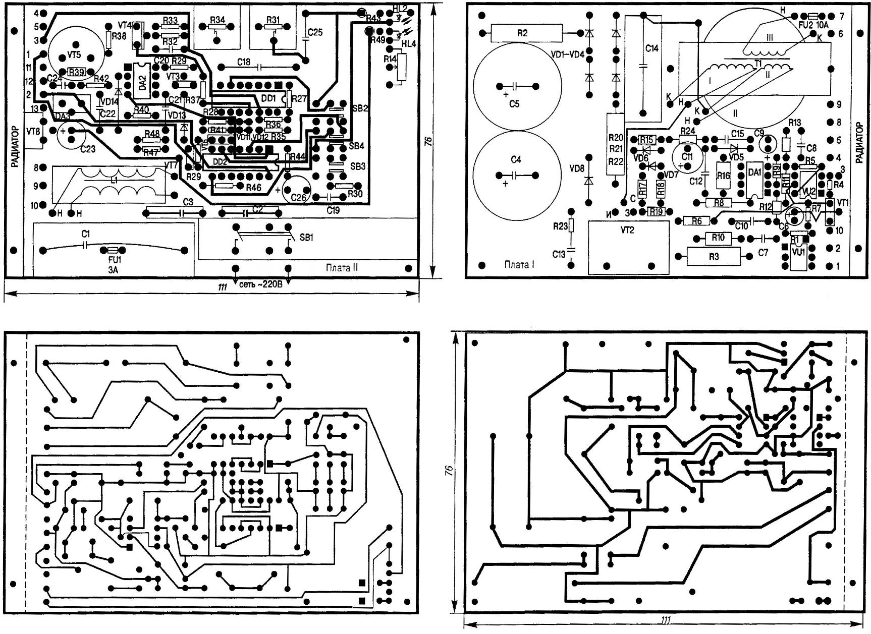
The topology of the circuit boards I and II (scale the image from the electronic components and the printed conductors)
To improve the performance characteristics of the device (including reduction in weight up to 900 g and reduce the housing dimensions to a minimum 80x80x150 mm) recommended the introduction of additional subunit into the design, with the installation of a small fan. It’s kind of a mini-forced cooling system for this instrument that provides adequate reliability of power semiconductor devices, even when using small radiators: dural plate 80x65x5 mm for VD9 and VD10, and ribbed heat sink, shortened to 30x22x15 mm for VT2. The rest of the electronics device, including the transistors VT5 and VT8, works flawlessly within the allowable modes without any radiators.
Now about the other features of the design. In the transducer applied a homemade inductors and the transformer. Winding L1 is 15-20 turns on the ferrite Н2000НМ К20х16х6 the two leads NGTH of 0.25. As T1 is used for the magnetic ferrite Ш11,5×14,5 chokes horizontal scan, already used in TVs, OPENCT. The winding, of course, need a new one. I and II completed in two, and III in seven wires. That is the primary winding at T1 should contain 91 round (ПЭВ2-0. 5×2), secondary — four turns of the same wire. And as last, the third coil need only nine turns (ПЭВ2-0,6×7).
The quality of winding should be given special attention. Coils should be stacked neatly, without overlaps; between the rows need to pave the paper. If the last row of any winding threatens to be incomplete, it is necessary to distribute the remaining coils evenly.
To avoid confusion, it is useful immediately to mark the beginning and end of each of the windings. But you can use the following, well-proven in practice method. Especially when the time for remarks seemingly neglected and the transformer is ready for installation in a particular construction.
The primary winding should submit the reference voltage with a low frequency generator (10-15, 5-15 kHz). Arbitrarily taking the “beginnings” and “ends” the rest of the findings, digital voltmeter mode in AC circuits find the true winding and record the value for each of them.
Then by the end of the primary winding is temporarily connected secondary. Measure the voltage relative to the known beginning of the “primary” and unattached “end” of the investigated pairs of outputs.
If the device detects in this experiment the increased value and temporarily connected the output is the true beginning, and I connected it to the (formerly free) — end of the winding. Conversely, a low voltage indicates that the arbitrarily adopted the names of the investigated pairs of outputs should be changed to their opposites. Likewise define the beginning and end of the third winding.
During Assembly of the transformer is necessary to provide a fixed gap 1.3 mm paving between the magnetic core and “symbiosis” frameless windings pieces of cardboard. As the current meter, it is recommended to use the pointer М4761 (it was equipped with once reel-to-reel tape recorders) with a homemade shunt R26 — cut nichrome wire (diameter 2 mm and length based on the required resistance, 0.1 Ohms). Before installation this appliance care should be taken to open and slip the arrow in the middle of the scale, then, in the course of operation of the device was to observe the charge and discharge of the battery.
Homemade device looks worse industrial:
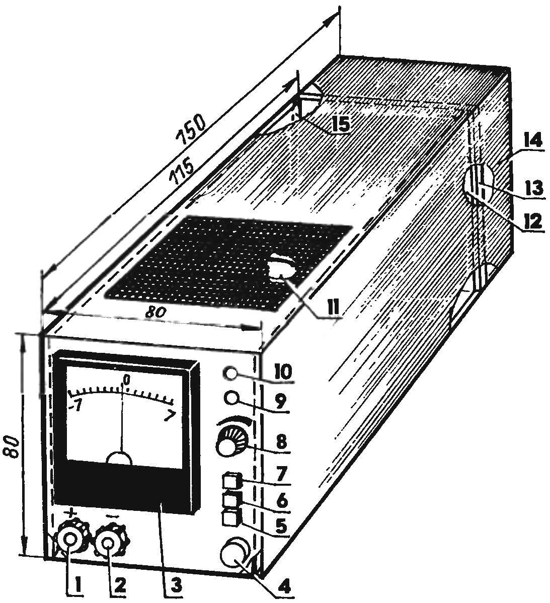
1,2 — terminals; 3 — dial gauge discharge-charge; 4 — button switch device in the home network; 5 — button START; 6 — switch MOMENTARY-MULTIPLE; 7 — the switch of the CHARGE-DESULFATACE; 8 — knob of the regulator the CHARGE CURRENT; 9 — led display. DISCHARGE; 10 — led indicator. CHARGE; 11 — fan forced cooling system; 12 — mounting plate II; 13 — plate cooling and radiator; 14 — compartment incandescent lamps; 15 — circuit Board I
Applied in the design of the diodes are in the majority — type КД226 with any alphabetic index at the end of the name. As VD8 is recommended to use КД206Д or equivalent, designed for a voltage of 600-800 V, direct average current of 1.7 A and a frequency of at least 30 kHz. Diodes VD9, VD10 in the original — КД213А (КД213Б). But, as practice showed, them for greater reliability it is desirable to replace a Schottky diode КД2997А (КД2997Б) or КД2999А (КД2999Б).
Optocouplers VU1, VU2 type АОТ127. It is important that the voltage was not below 500 C. Instead of KT315 transistors specified on the circuit diagram, are reasonable, any of the series КТ312, КТ316, КТ3102, designed to work in devices with a voltage of 30 V. the Transistor VT5 — КТ801А (КТ801Б), other types of semiconductor triodes here undesirable. But the place VT8 acceptable КТ819 with any alphabetic index at the end of the name.
The fan used on IBM PC-GI-486-12v. Trimmer resistors R31, R34 — multi-SP5-2, and the Adjuster (R14 — type SPZ-4am. As constant resistors of MLT acceptable and their numerous counterparts, matching of power dissipation and the values are conventionally marked on the circuit diagram. The role of capacitors C1, C13 and C14 is the best fit К78-2, in place of S2, Sz successfully work K15-5, designed for a voltage of below 600V, C4 and C5 — 100 UF ur = 400 V or single 220-microfarad 400-volt C50-32. The rest of the electrolytic capacitors commonly used K50-35, and nonpolar — of any type.
The device is assembled on two PCBs 111x75x2 mm bilateral foil of the PCB or Micarta. Hard their fixation in the housing is achieved by means of aluminum angle to the front panel, and using a plate cooling and radiators to the wall durable metal case with top vents and rear — compartment under incandescent. Everything is so captured from above an air flow blowing on the radiator of the transistor VT2, resistors R20—R22, and passed through the holes of the plate radiator of the diodes VD9, VD10, cooling the valves themselves, and then — and incandescent lamps EL1, EL2, and then seamlessly throw a block in its rear part.
If the installation is made in strict accordance with the schematic electrical diagram from a known good radio parts, the device usually starts working immediately. However, to neglect the adjustment of the threshold Comparators in most cases, I think, not worth it. And the algorithm to perform such an operation is quite simple.
First turn of the cartridges of filament lamps EL1 and EL2 (to reduce load) and is connected to the regulated power supply terminal of the device, derived on the front panel. Putting on the power supply 10.5 V, trimmer R34 achieve the appearance of illumination HL1 — indica. CHARGE. Then set the voltage to 14.2 V, and adjustable “podstroechnye” R31 reach a point when HL1 off. Then screw in cartridges of filament lamp (EL1, EL2) and… Pulse automatic retragerea device can reasonably be considered set and ready for reliable work!
S. ABRAMOV, Orenburg
Recommend to read
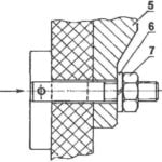 TRICKY BOLT
In carrying out various construction works it is often necessary to install and mount on wall panels are quite large and heavy products, devices and other structural elements. In...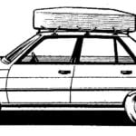 THE TRUNK PLUS CASE
For the motorist the trunk of the car is not only convenience, but also a number of related problems. And first of all — observance of the required aerodynamics. The fact that in...
