 The proposed device allows you to charge any rechargeable batteries with voltage from 1.2 to 15 V and a nominal capacity of from 0.05 to 20 A·h and can be widely used in radio, car owners and even users of electronic equipment. The device is a charger (current stabilizer), which uses a pulse-frequency regulation, which eliminates the need for bulky heat sink from the control transistor.
Schematic diagram of the device determines its circuitry which includes a transformer T1 VD1 rectifier with filtering capacitor C1, a parametric stabilizer R1VD2 the multivibrator transistors VT2 and VT3 with the current amplifier transistor VT4, the composite transistor VT5 VT6 operating in the switching mode, the inductive-capacitive filter L1C3, switching diode VDЗ. The resistors R14 — R25, R7, the transistor VT1 forms a chain of negative feedback.
The device operates as follows At power-up the capacitor C3 is discharged, the transistor VT1 is closed, the multivibrator generates pulses at a frequency of about 20 kHz. Reinforced transistor VT4, the pulses of the multivibrator to open the composite transistor VT5 — VT6. When this transistor is open, current flows through it, the inductor L1 load GB, connected to the connectors X1 and x2, the resistors R14 — R25 (depending on the selected switch ЭА1 limit the charging current) and the capacitor C3. When closing the transistor VT4 current of self-induction of the inductor L1 is applied through the switching diode VD3, capacitor C3, and the load resistors R14 — R25.
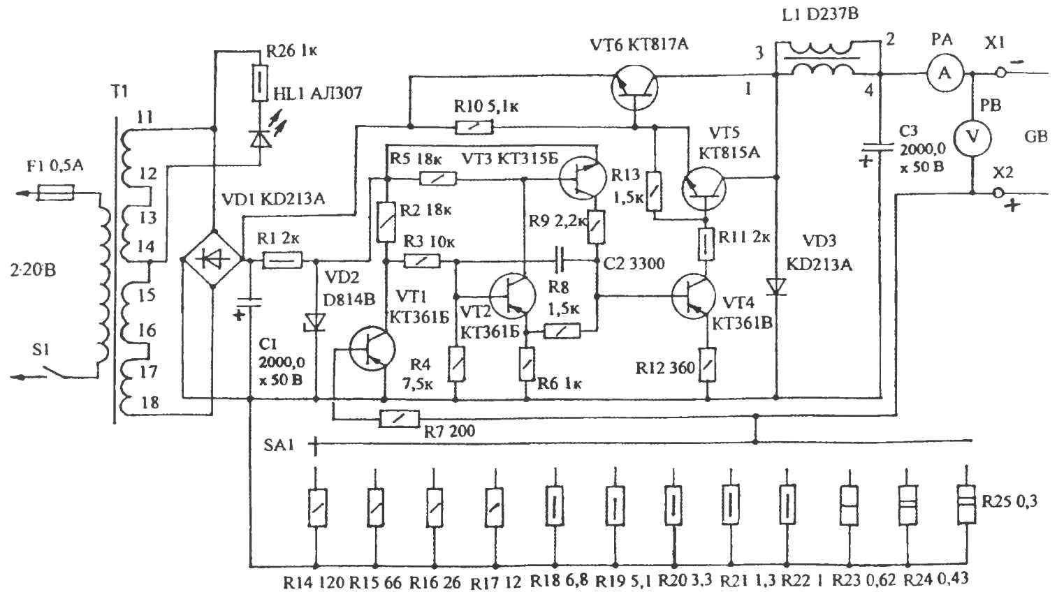
Circuit diagram of charger
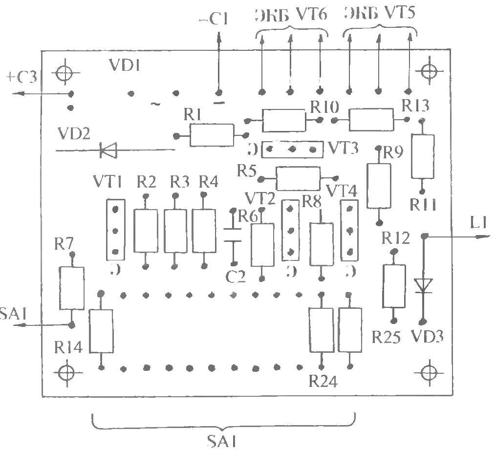
Wiring diagram
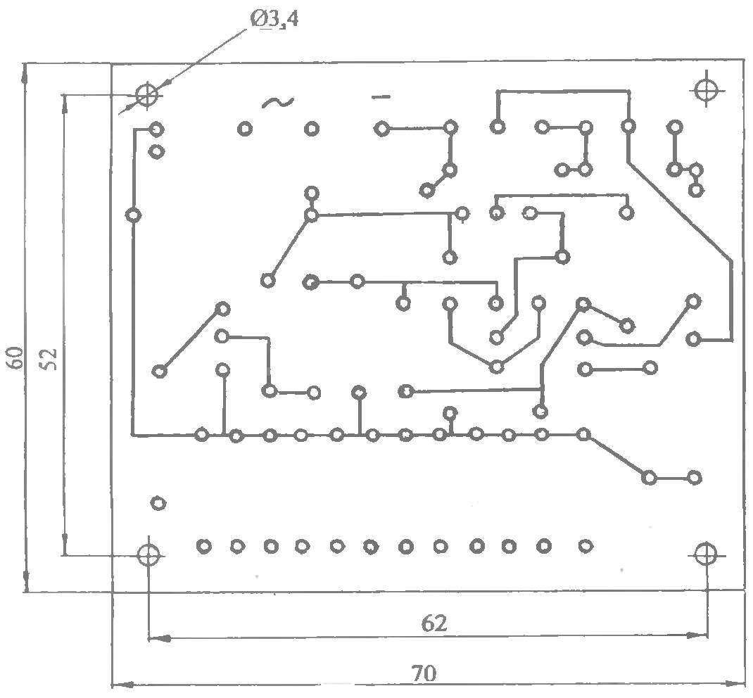
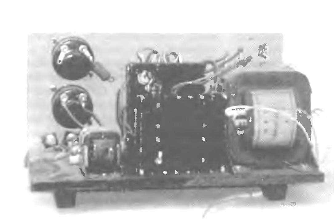
A printed circuit Board,
After several pulses of the multivibrator, the voltage drop across the resistors R14 — R25 reaches 0,65 V, the transistor VT1 is opened and operation of the multivibrator is terminated. In the steady state, decreasing the current load, the voltage drop across the resistors R14 — R25 decreases, the transistor VT1 is closed and the multivibrator produces one pulse duration of 20 µs. Then follows a pause from 0,045 up to 4.5 MS (depending on the value of the load current). Then the cycle repeats.
Establishing device is reduced to the careful selection of the resistors R14 — R25 determining current charging of cells or batteries. Most of the details of the device described is mounted on a printed circuit Board from foil fiberglass 2 mm thick. the Transistor VT6 is mounted on the heat sink and it pressed the transistor VT5.
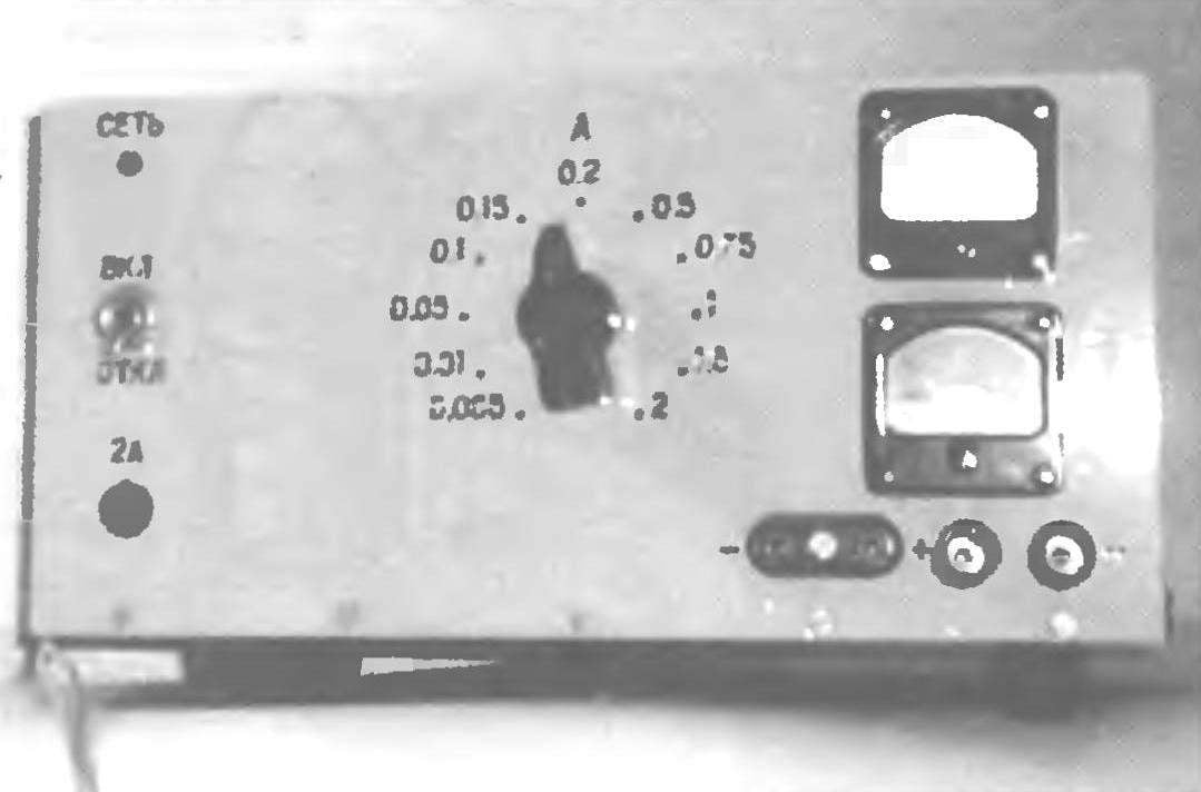
Structurally, the device consists of a base, panels, covers.
Base dimensions 240x120x6 mm, made of vinyl plastic. On it are mounted: the transformer T1, inductor L1, capacitors C1, C3, radiator cost, radiator with diodes. Radiators put to the ground through the bushing with a height of at least 5 mm. from the Bottom of the base attached rubber “glides”. Preferably under the radiators to improve ventilation is to drill a few holes.
The layout of parts, circuit boards and instrumentation of the charger to the base and front panel
Panel sizes 240x120x3 mm, made of aluminium AMr 3. On it are mounted: network switch S1, fuse holder, led HL1, the switch SA1 current charging, voltmeter, ammeter, output terminals. The panel lettering is made with engraving. The panel is attached to the base with M4 screws.
Cover made of steel sheet with a thickness of 0.5. It has vent holes and is attached to the base by M3 screws.
The heatsink under the transistors has a size 90x70x14 mm with a rib height of 10 mm. Radiator under the diodes КД213А has dimensions 70x70x14 mm with the height of the ribs is 10 mm.
Transistors put on the heat sink on the paste KPT-8. The diodes put the radiators on pasta KPT-8 through pads. Diode VDЗ mounted on the reverse side of the card and attach it to the heatsink of transistors through a pad also paste KPT-8.
This design is used (or can be applied) the following details. The transformer T1 is the CCI-220-50. Perhaps the use of a homemade transformer with the following data: Ш20х20 magnetic core, the coil 1 must contain 2000 turns of wire PEV-1, diameter 0.25 mm, and the winding 2 has 300 turns of wire sew-1 with a diameter of 0.75 mm. Choke L1 — Д237В, but you can use homemade. It needs to have an inductance of 5.5 mH, the magnetic Ш20х20 ferrite 2000NM brand with 250 turns of wire sew-1 with a diameter of 1.5 mm. Between its sh-shaped halves is placed a gasket made of PCB thickness of 1.2 mm.
Resistors C2-33, MLT, OMLT. Resistors R22 — R25 C5-16MV. Capacitor C2 is of type K10-17A-М750. The capacitors C1, Sz, type K50-6, K50-16, K50-24, K50-29, designed for a voltage of less than 50 V. the Switch S1 — type МТД1. Switch ЅА1 — type PGK, PGG-11P-1N. Holder fuse — type ДВП4-1V. Voltmeter and ammeter — type M4203. Output terminals of ZMZ.
КТ815А transistor can be replaced by КТ817А and КТ817 on КТ819 in a plastic housing.
The fee is designed to fit the diode bridge type КЦ410А. This design used the bridge, assembled on the diodes КД2213А installed on radiator Led HL1 — type АЛ307 or the like with a working current of 10 mA.
Main technical characteristics
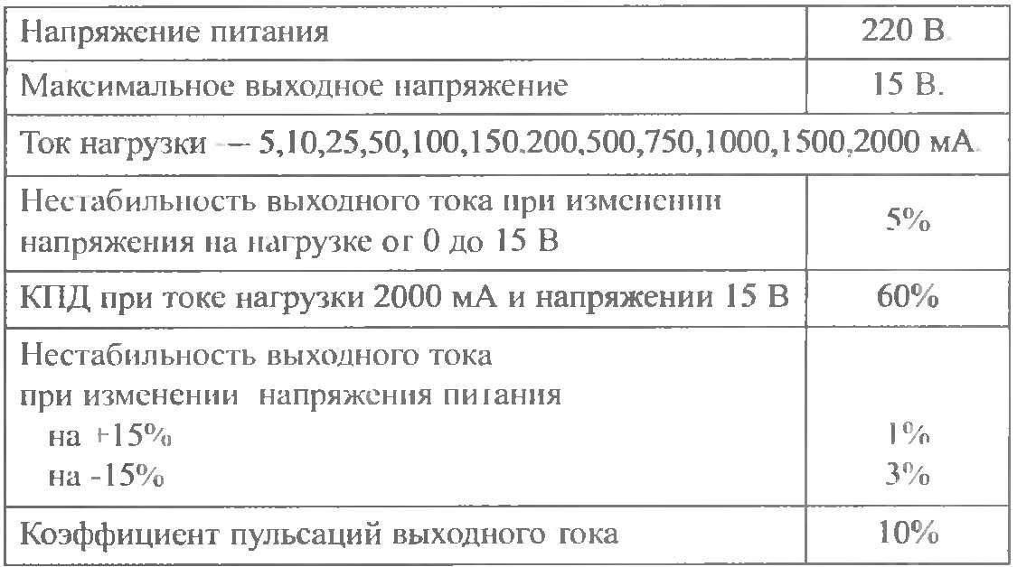
Ammeter — a current of 3 A. the Voltmeter for a voltage less than 50 V, as when you turn on the charger with no load the output will be about 42 volts. When you turn on the load, the voltmeter will show the voltage, which at the moment is on the battery terminals.
Remember that to recharge the battery a current of 0.1 of the nominal battery capacity.
Y. KURBAKOV, Tula
Recommend to read
 ERASER INSTEAD OF SODA
The different orders had to perform for the last time a Cup "Junior technician", school № 81 of the city of Gorky. This one was especially unusual and interesting. Heads of school rooms... YEAR-ROUND ASSISTANT
Fifteen years subscribed to the magazine "modelist-Konstruktor" and in each room find a lot of interesting and useful articles. By education I am a mechanical engineer and I am...
