 Control line model plane-vysokoplan. The first simplest kordovye model. made of pair plates, quickly bored novice modelers — they, of course, want to raise in the air like a real airplane.
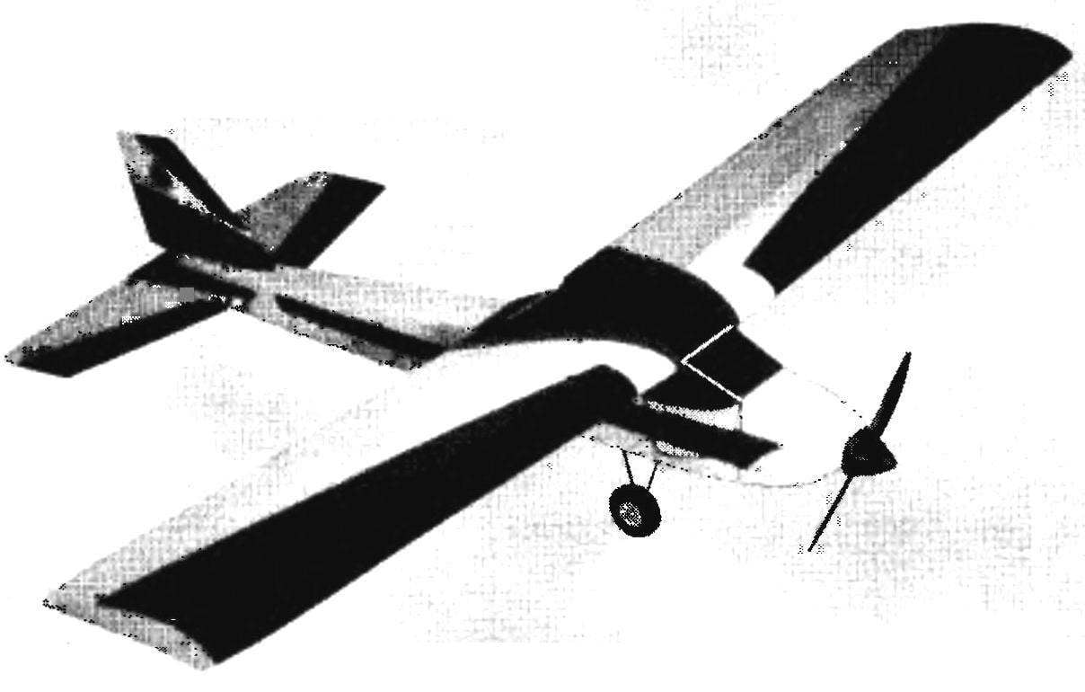
We offer you a nice control line model aircraft-high wing, which looks great in flight and has good handling qualities despite the relatively low-power engine is 1.5 CC MK-17 “Junior”. The model is made with minimal use of balsa is used mainly phony veneer and pine slats.
The WING model set consists of 12 ribs, lime sawn from plates with a thickness of about 3 mm, pine dvuhromovo spar and front and rear edges. Wing Assembly is made on the stocks, consisting of a flat Board base and two rails along the front and rear edges; their thickness is chosen such that the chords of the ribs, based on them, and, accordingly, the plane of the chord of the wing occupied a horizontal position.
Build customized parts are softened (slightly diluted with acetone) epoxy glue. On the axis of symmetry of the wing, glue two fake boss, which is drilled hole of diameter 3mm through them when building the model, skip the wing bolts to the fuselage. Itself the Central part of the wing is sheathed with a phony veneer thickness of 1 mm.
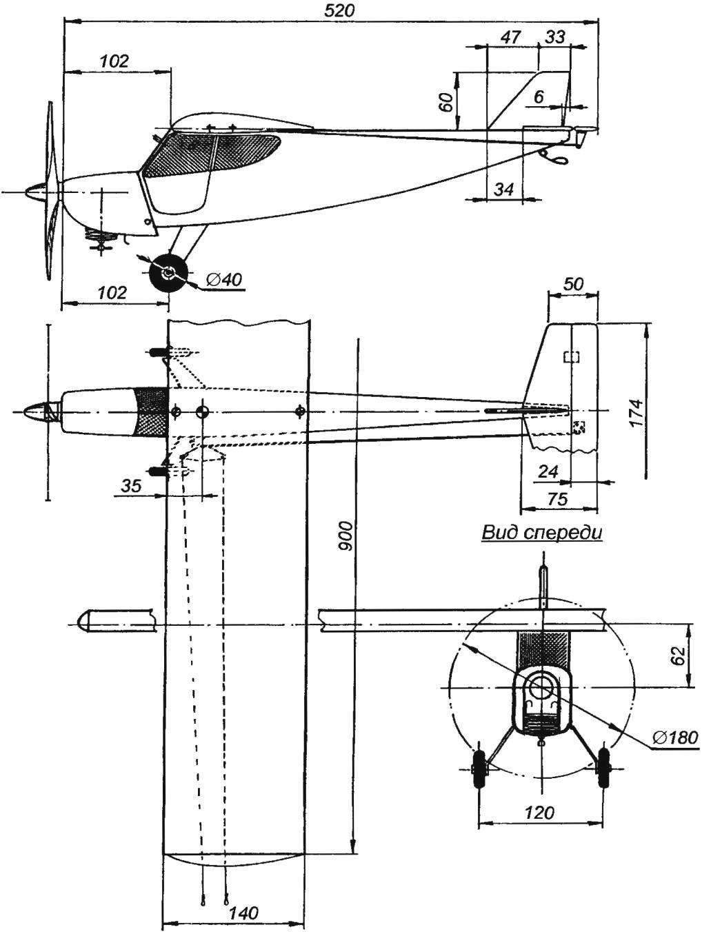
Geometric diagram of the córdoba aircraft model-high wing with engine MK-17
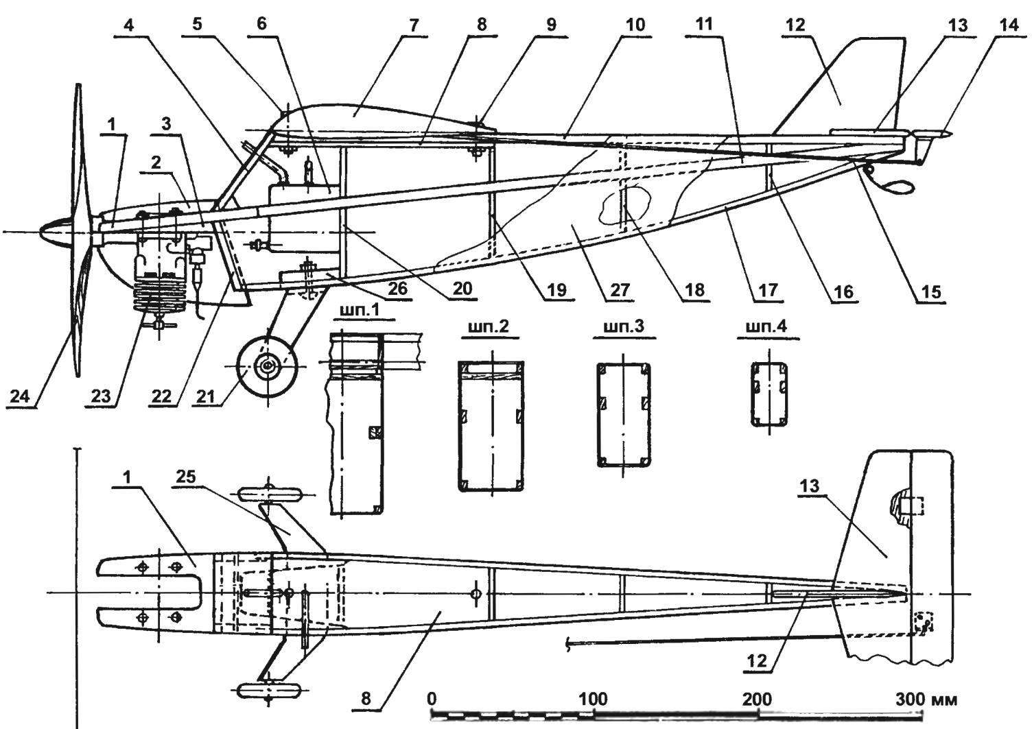
Linking cord model (on the planned projection of the wing, the bonnet and the engine is not shown):
1 — engine mount (beech, s8 plate, lined with 1 mm plywood); 2 — hood (Vileika of fiberglass in epoxy binder); 3 — wedge (beech); 4 — front wall (Linden, plate s3); 5,9 — wing mounting screws; 6 — fuel tank capacity 50 ml; 7 — wing; 8 — base of the cradle wing (plywood s4); 10 — upper stringer (pine, rack 5×5, 2); 11 — longitudinal (pine, 10×3 rail, 2 PCs.); 12 — keel (balsa s4); 13 — stabilizer (balsa s4); 14 — the Elevator (balsa s4); 15 — control rod (aluminum wire Ø2); 16 — frame № 4 (Linden, plate s3); 17 — the lower stringer (pine, rack 4×4, 2 PCs.); 18 — frame № 3 (Linden, plate s3); 19 — frame № 2 (Linden, plate s3); the 20 — frame No. 1 (Linden, plate, s3); 21 — wheel chassis; 22 — lower baffle (lime, plate, s3); 23 — engine MK-17 “Junior”; 24 — propeller Ø180; 25 — spring chassis (duralumin D16T, s2); 26 — landing gear (beech); 27 — fuselage skin (veneer basswood s1)
Assembled wing Marquesa (aligned) with sandpaper glued on a flat rail. After that, between the shelves of the spar with epoxy glue fixed node, the control arms of consisting of a body stitched together from the phony rails, steel axle, a pair of remote fluoroplastic bushings and actually rocking carved from duralumin D16T.
Next on the rocking chair fixed cables management that appear through the holes easier in the ribs and holes in foam wingtip.
The finished wing is fitted by a Mylar film thickness of 25 µm with the help of glue “Moment” and the usual iron or hair dryer (on standard technology, often described in the journal “modelist-Konstruktor”).
The FUSELAGE. The basic power elements of the fuselage are the four fake frames, four stringers of pine and two pine spars. Motor mount cut from beech plates 8 mm thick and lined on both sides with 1 mm plywood, tied to the longerons of the fuselage, the front wall of the fuselage frame No. 1.
Fuselage Assembly is made on the staple in the inverted position. The slipway is laced with plastic wrap flat Board section approx 150×30 mm, which marked the plane of symmetry of the fuselage and the axis of the frames. For mounting on the stocks of frames are used pieces of rails with cross-section 20×20 mm and length of about 40 mm nails nailed to the stocks so that between each pair tightly included corresponding frame.
Next to fixed so the frames are attached with pins and clips, engine mount, longerons and stringers. After a thorough inspection of correct Assembly and symmetry of the frame, all joints are glued plasticized epoxy glue.
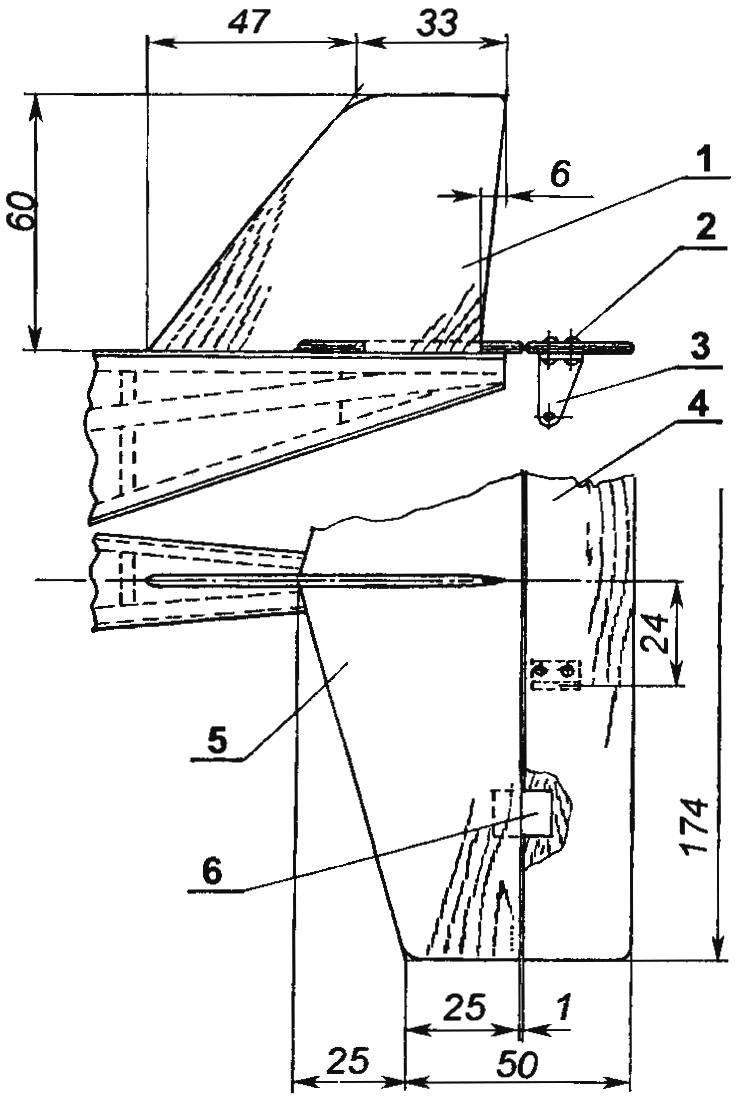
The tail of the model:
1 — keel (balsa plate s4); 2 — rivet (soft aluminum wire Ø1); 3 — horn of the Elevator (duralumin, sheet s2); 4 — the Elevator (balsa plate s4); 5 — stabilizer (balsa plate s4); 6 — hinge linkage of the Elevator (nylon braid)
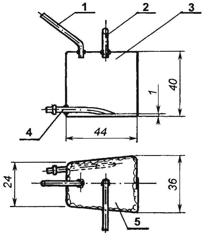
Fuel tank:
1 filling tube (copper tube 4×0,5); 2 — drain pipe (copper, tube 4×0,5), 3 — sides (tinplate s0,3); 4 — supply pipe of the engine (copper, tube 4×0,5); 5 — upper and lower lids (tinplate s0,3)
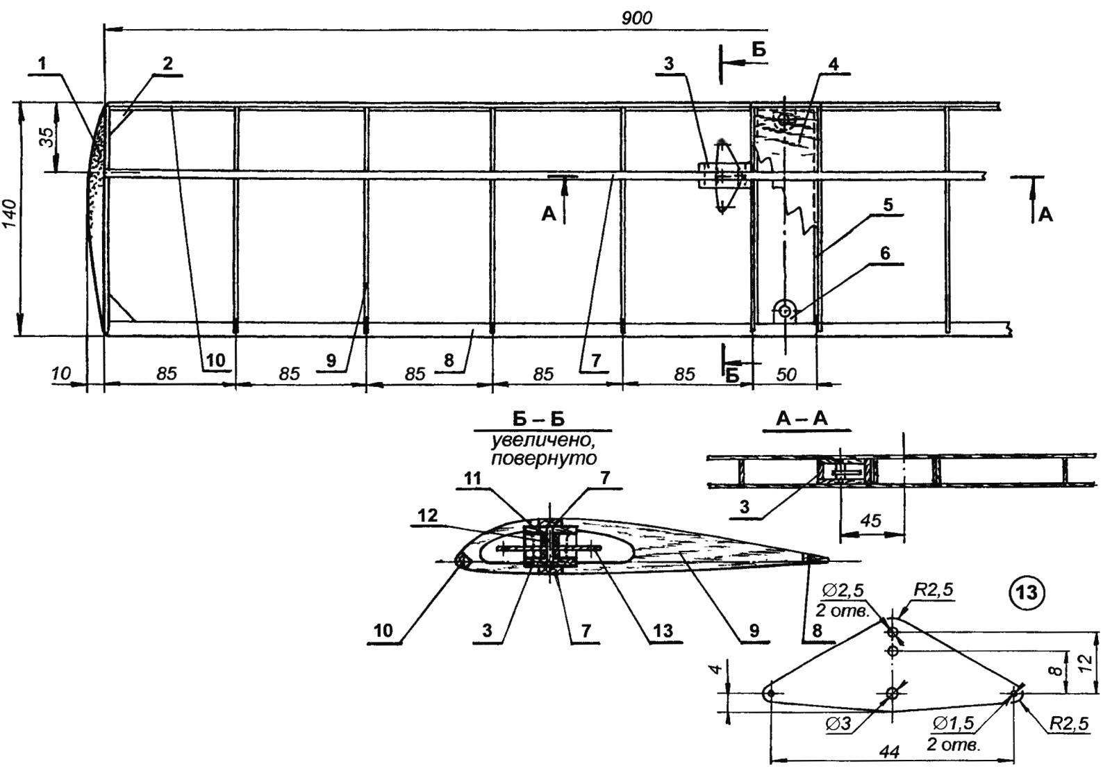
Wing:
1 — wing tip (foam); 2 — solitaire (Linden); 3 — the case of the node, the control arms of (a Linden, a rake 15×3); 4 — a lining of the center (Linden, an interline interval s1,5); 5 — base of the sewing center – (Linden, plate s3); 6 — boss (lime, 2); 7 — spars (pine, rail 10×3); 8 — trailing edge of the wing (pine, 12×6 rack); 9 — rib (Linden, plate s3, 2 PCs.); 10 — front edge (pine, rail 6×6); 11 — axis of rocking of the control (steel, wire Ø3); 12 — spacer (PTFE, 2); 13 — rocker control (duralumin, sheet s2,5)
The finished frame is aligned to it stick a fake front wall and bottom wall, the plywood base of the cradle wing taped to his nuts with M3 thread for mounting of the wing, and beech springs support the chassis, also with a sealed 3-mm nuts. Next, the fuselage is glued 1 mm fake veneer, but before this operation it is necessary to fix in the front compartment fuel tank, soldered tinplate with a thickness of 0.3 mm. While the filling tube is discharged through the front wall of the fuselage, and drainage through the left sidewall. Elastic supply pipe of the engine is output into the engine compartment through the bottom wall.
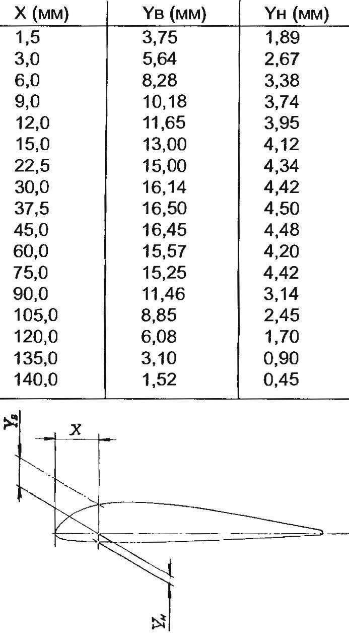
The table control section of the wing profile (P-II-14%)
Ready vyshkurivaetsya fuselage top stringers in the wing mounting area is pruned according to his profile, and the surface of the fuselage podsalivaya and painted with enamel. The final stage of finishing is coating two-component parquet lacquer to protect the paint surface from dissolving its fuel.
The TAIL Assembly consists of celebarty fin and stabilizer were cut from the plates 4 mm thick. the Elevator is attached to the stabilizer on the hinges, representing segments of a tight nylon webbing, glued in the grooves of the stabilizer and rudder.
CHASSIS model leaf, with plastic wheels with a diameter of 40 mm, taken from a children’s toy. Spring cut from aluminum strips with a thickness of 2 mm; the fuselage it is attached by a pair of screws with thread M3.
The tail spikes of 2-mm steel wire.
The HOOD is fiberglass, wikiepedia on the master model consists of three layers of fiberglass cloth on the epoxy binder. The master model cut out of foam, puttied up the clay and covered with a release — supermonkey cling film used for packaging products. After polymerization of the resin hood vyshkurivaetsya and covered with enamel. Used for mounting elasticity fiberglass shell — piece is securely “snaps” on the fuselage when the bonnet vents coincide with the semi-circular projections (heads of self-tapping screws) on the fuselage.
FINISH of the model is carried out using self-adhesive color films. In particular, look good carved from a dark film and glued on the fuselage “Windows” and “doors” and colored longitudinal bands on the sides of the model.
I. SOROKIN
Recommend to read
 PORSCHE 911 CARRERA CABRIOLET
The legendary PORSCHE 911 was built in 1964 and is still producing cars with "911" is the Foundation program of the company Porsche. The first version of this car was equipped... BASED ON “RHYTHM”
In many circles of modeling, there is a shortage of good compression motors a working volume of 2.5 cm3. The only satisfactory engine KMD-2,5 for the last time so decreased that the head...
