
 What is the kit-the fan does not dream to collect small-sized power source? But here everything depends on the power transformer: it-largely determines the dimensions of the power supply. If you try to make a transformer with a minimum size of, for example, with a magnetic core Ш12Х12, provided that the voltage of 220 V, the number of turns of the primary winding will be approximately 7600.
However, excessive stress can be redeemed by using the resistor in series with the coil, but in this case dissipates significant power. Another thing — the capacitor in the AC circuit. Depending on the frequency capacity has the properties of a reactive (capacitive) resistance. However, the energy received by the capacitor during its charge almost completely returned to the current source and almost never lost.
Now, using the properties of the capacitor, it is possible to reduce the number of turns of the network winding of the transformer, partially cancel the incoming voltage.
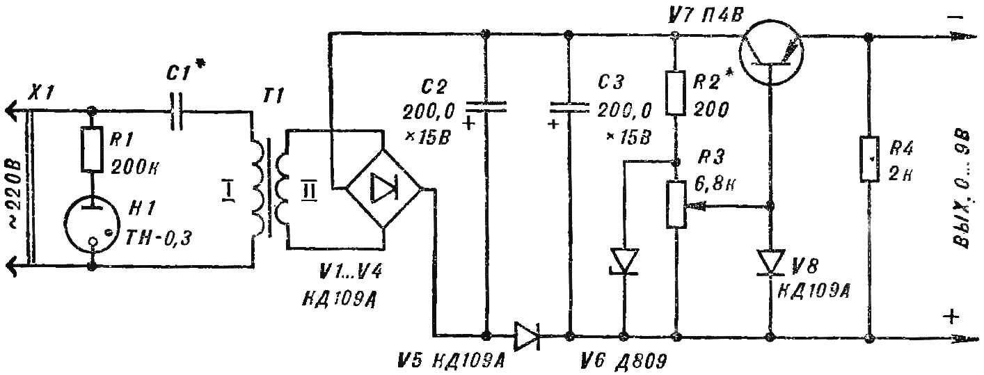
Fig. 1. Schematic diagram of the power supply.
Figure 1 is a schematic diagram of a compact voltage regulator for power devices where current does not exceed 120-150 mA. Power transformer T1 is designed for a maximum power of 3 watts, has a core Ш12Х12 (cross-sectional area SC of = 1.3 cm2). You need to pay “extra” voltage of 160 V. the current in the circuit will be:
I = 1,1*(RTR, W)/(U, V)=1,1*3/160≈0,02 A=20mA.
The capacitance of the capacitor C1 is:
C1=3,2(I,AI)/(U,V)=3,2*20/160=0,4 µf;
Then the “remaining” voltage 60 V will need to wind
W1=45*U/Sc=45*60/1,3≈2000
of turns of wire sew-1 0,08—0,1. Given that the voltage at the secondary winding 12, it consists of 405 turns of wire PEV-1 to 0.2.
Similarly, you can make a transformer with other parameters. For example, if the load current is 50 mA, then it is easy to determine what value of C1 will be a 0.22 UF, and the diameter of the wire of the secondary winding is 0.16 mm.
The output voltage of the stabilizer varies from 0 to 9 V. the Resistors R2, RZ and diode V8 form a voltage divider in the base circuit of the transistor V7. When you move the cursor up resistor RZ scheme to the base receives a negative potential and the output voltage of the stabilizer increases.
Thanks to the chain C2, C3, V5 is the amplitude of the output voltage ripple is negligible and the stabilization factor is 300-400.
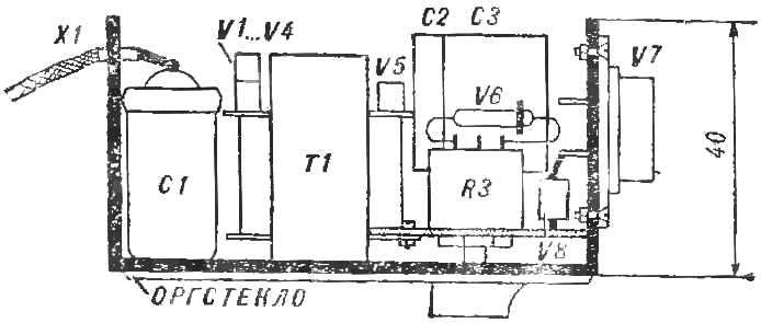
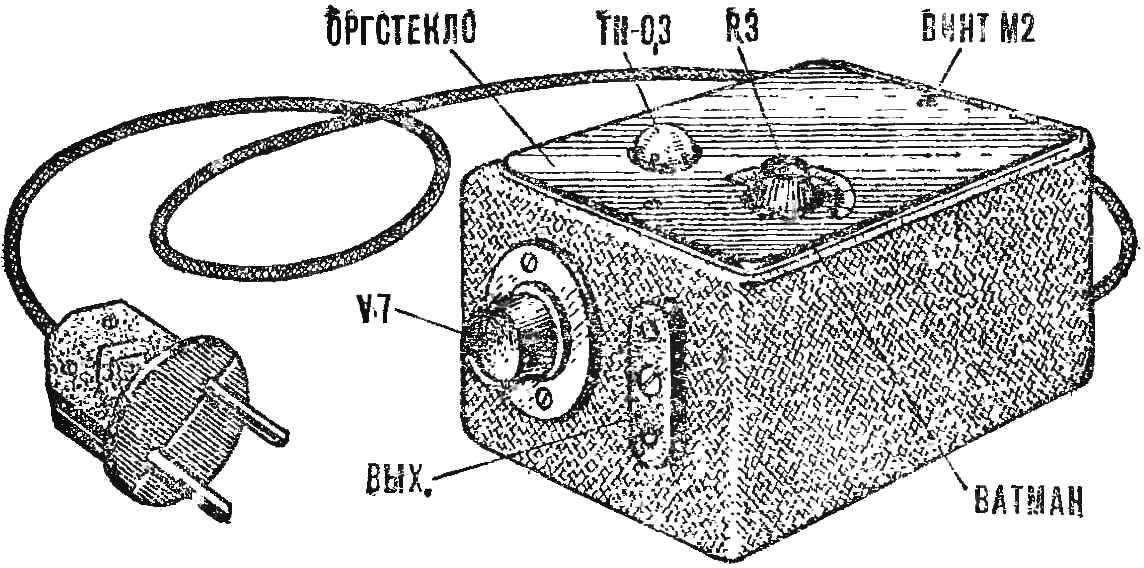
Fig. 2. Placing parts in the housing.
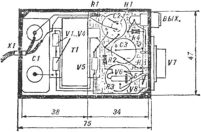
Fig. 3. Wiring diagram power source.
Configuring the stabilizer is reduced to the selection of the value of the resistor R2 with the aim of obtaining the maximum stabilization factor. The output resistance of the stabilizer 18 Ohms. The transistor has B = 50-60. It can be replaced by another from the A4. With the heat dispersion area of 15-20 cm2 work well transistors П213, П201. The capacitors C1 — MBGP with an operating voltage of 400 V, S2, Sz — K50-6. Resistors R1, R2, R4 — MLT-0,5, variable resistor RZ — SP-0,4. The diodes V1 to V5, V8 can be replaced by КД105, D226 with any alphabetic index. Case size 75Х50Х40 mm made of plastic boxes. Location of circuit elements in the unit shown in figures 2 and 3. All connections between parts are made bare tinned wire Ø 0,8—1 mm.
The efficiency of the device check the input voltage in the range 190-230 V. Selecting the value of resistor R2 sets the DC voltage at the output independent of fluctuations in input. Circuit Board attached to the transformer screws M1. Under the “neonka” in the circuit Board drilled hole Ø 9.5 mm. the Diodes V1—V5 mounted on a frame of the transformer with glue BF-2.
In accordance with the voltage on the meter on the drawing paper applied the scale of the variable resistor and is closed by a transparent Plexiglas 2 mm thick.
A. MEDVEDEV, Krasnoperekopsk, Crimean region.
Recommend to read
 SLIDES WITH NEGATIVE
Affordable and easy to use automatic cameras-"soap" can make any person a photographer. The presence everywhere for the service of photographers specialized items the most famous foreign... “RESUSCITATION” BOOTS
Did not dare to write in a journal until I met a few tips, which at the time he thought of and successfully used. So we are — with a mustache? I am sending your advice on how to repair...
