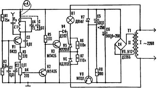
The basis of a capacitive relay — a low-power generator of high frequency such as local oscillator of a radio receiver. To the circuit L1C4 (see diagram) of the connected metal plate sensor. Approached to him the palm of the hand represents the second plate of the capacitor CD. The capacity of such a condenser is the greater, the more area it covers and the smaller the distance between them.
The planimetric L1 coil wrap on the frame Ø 8-9 mm, glued paper. The coil contains from 22 to 25 turns of wire sew-1 0,3—0,4 wound in a single layer turn to turn. Make the withdrawal from the 5-7th round, counting from the beginning (marked point).
The device operates from a stabilized power supply or from two or three batteries 3666Л, connected in series.
Include in the collector circuit of the transistor V1 milliammeter to the current 5-10 mA. And that using the device did not pass the high frequency component of the collector current, between the point of connection of the milliammeter with the coil L1 and the emitter voltage V2 will include a capacitor with a capacitance of 0.01—0.5 UF (the diagram shows dashed lines). Sensor temporarily disconnect the alternator and test it. Watching the hand of the milliammeter, a short tail circuit L1C4. Collector current V1 should be sharply reduced: from 2.5—3 to 0.5—0.8 mA. Pokazana correspond to the greatest generation, the least — its absence. If the generator is excited, reconnect the sensor — plate and slowly lift the palm. Collector current decreases to 0.5—0.8 mA.
Weak current change amplifies the two-cascade amplifier on transistors V2, V3. And in order to manage the load in a contactless manner, the output stage capacitive relay SCR is made V5.
The engine of the variable resistor R4 set to the low () position. And then slowly move up until, until I turn on the signal lamp H1. Now hold your hand over it, made the plate and check the operation of the capacitive relay as a whole.
Diode V4 in the circuit of the control electrode of SCR V5 eliminates the appearance of the pulse reverse voltage. And the diode V6 and the resistor R7 protects the SCR from breakdown due to reverse voltage. For SCR with a valid Uо6р. = 400 elements V6 and R7 can be eliminated.
With SCR КУ201К or КУ201Л load current should not exceed 2A.
It is desirable that the load current was below the maximum allowable forward current through the SCR, as it is used in the condition of the limit modes reduces the reliability.
If, however, apply the symmetric triode thyristors (triacs) КУ208В or КУ208Г, the load current can be increased to 4-5 A. And thyristors КУ202Ж, K, L, M, N is possible to control the current to 10 A. In this case, the diode V6, the maximum allowable value of the direct current must comply with current controlled loading.
Transistor V1 can be replaced by П401—П403, П416—П416Б, П422—П423; V2, V3 — MP40—МП42, and V8 — МП37А, МП37Б, MP38, МП38А.
Resistors R5—R7 — MLT-2, others — of any type.
Capacitors C1—C3 — MBM, C5, C6 — K53-1.
Instead of the diode V4 will fit Д219А, Д220, Д220А, Д220Б or at least D226.
V9—V12 are interchangeable on D7, D226, КД105 with any alphabetic index.
The Zener diode V7 can be replaced by Д811.
N. MUSTAFAEV, G. Shani, Azerbaijan SSR
Recommend to read SILVER TREE To create new year's mood does not necessarily set the house a big tree. Moscow designer Marina Vinogradova offers its miniature version: it made their hands soft food foil layers strung... VOLVO S80 2,9 Firm Volvo in 1998, has chosen the Moscow international motor show for the premiere of his new sedan VOLVO S80. This car is rightly called the flagship of the company. The fact that the... 
 The basis of a capacitive relay — a low-power generator of high frequency such as local oscillator of a radio receiver. To the circuit L1C4 (see diagram) of the connected metal plate sensor. Approached to him the palm of the hand represents the second plate of the capacitor CD. The capacity of such a condenser is the greater, the more area it covers and the smaller the distance between them.