
 Summer — time for vacation and travel. During this period, there is a special need for a universal power supply for various mobile (and not only) household appliances.
Such a device was constructed in the circle of technical creativity of the Ulyanovsk technical College. Reliable, compact, and besides, it is powerful enough it can work equally well even in direct (with the voltage from 220 to 12 V), though in the opposite direction (when converting the 12-volt voltage 220V) as push-Pull in a children’s story (but electronic).
Of course, we are not talking about a simple Converter in the form of only one transformer. With the low voltage often required not AC, and the rectified or voltage (for example, charging a car battery, vehicle battery). So, can not do without a special device made on one or more electric valves that regulate the movement of electric charges so that the current through the load could proceed in one direction only.
As electric valves can handle, in particular, semiconductor diodes, rectifier properties are due to the work of the so-called p-n junction. Detailed materials on this and repeatedly discussed in the journal “modelist-Konstruktor” (see, for example, publications in № 10’82, 1-2’92, 7 -9’93, 5’97, 11 ’99, 10 -11’02).
Of particular interest is the circuit design of the voltage Converter, whose output is full-wave rectifier in a diode bridge (Fig. 1). Four shoulder such a rectifier to form at least two parallel branches, two semiconductor valve with their p-n junctions in each.
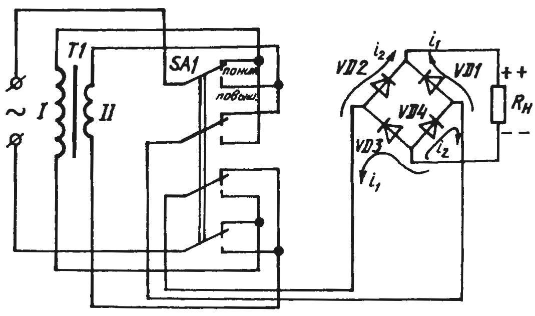
The principle of converting AC voltage into a low (high) permanent with one transformer with rectifier bridge
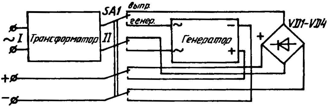
Possible electronic architectonics of the umformer for change peremennogo voltage into a low DC and Vice versa
When on the top (the scheme) the output of the secondary winding has a positive half wave of the AC voltage, the current practically without losses goes through the diode VD1 to the load, returning on (also without any additional losses in the diode VD4) to the lower coil terminal. P-n transitions of a pair of semiconductor valves are working in the so-called forward direction. Via VD2 and VD3, the current can not go, because this is prevented by the corresponding p-n transitions, the current (in this case) in the opposite, reverse direction.
In the next half-cycle when positive half-wave AC voltage appears at the bottom (under the scheme) the output of the secondary winding of the transformer, the role of the parallel gate branches in the diode bridge reverses. And the current is already supplied to the load through the open VD2, and goes to the lower coil terminal through VD3. The diodes VD1 and VD4 are in non-conducting (closed) condition, since p-n-junction each of them in this moment — not literally, but in the opposite, reverse direction.
However, until electronic “push-pushing” the transformer even with such a rectifier is “not up”. Indeed, in accordance with the original design of our device should work as umformer, that is, with perhaps less loss convert electricity network (220 V, 50 Hz) rectified voltage of 12 V and when you turn “backwards” to get from any 12-volt DC source 220 In the desired frequency to power model television, radio or electrical appliances with power up to 100 watts.
It turns out that to make the intended device by adding, for example, already considered the schematic switch with semiconductor subblock generator that converts 12-volt DC voltage into pulses, which after transformation will allow the primary winding to remove 220, in the form close to sinusoidal with a frequency of 50 Hz (Fig. 2).
A circuit diagram of such a “push-pushing” (Fig. For) requires no expensive electronic components or a lot of experience in the installation and commissioning works. The basis of the generating subunit is the multivibrator of the two transistors VT3 and VT4, operating at a frequency of 50 Hz with a supply transform DC 12V in socket INPUT CONVERSION.
Semiconductor triodes VT1, VT2 and VT5, VT6 act as powerful amplifiers, loaded (when you switch “mnogomernogo” switch SA1 is in the on position CONVERSION.) for 10-volt windings II-1 and II-2 of the transformer T1. Well, I removed the windings, the resulting voltage (220 V, 100 W, 50 Hz), for protection from overloads and short-circuit protection fuses FU1 with a thermal fuse of 0.5 A.
Semiconductor diodes VD1 and VD2 with capacitors C3 and C4 serve to improve the pulse shape at the time of opening of transistors VT1 and VT6. The inclusion of the generator in the work signal indicator light CONVERSION. on the front panel of the device.
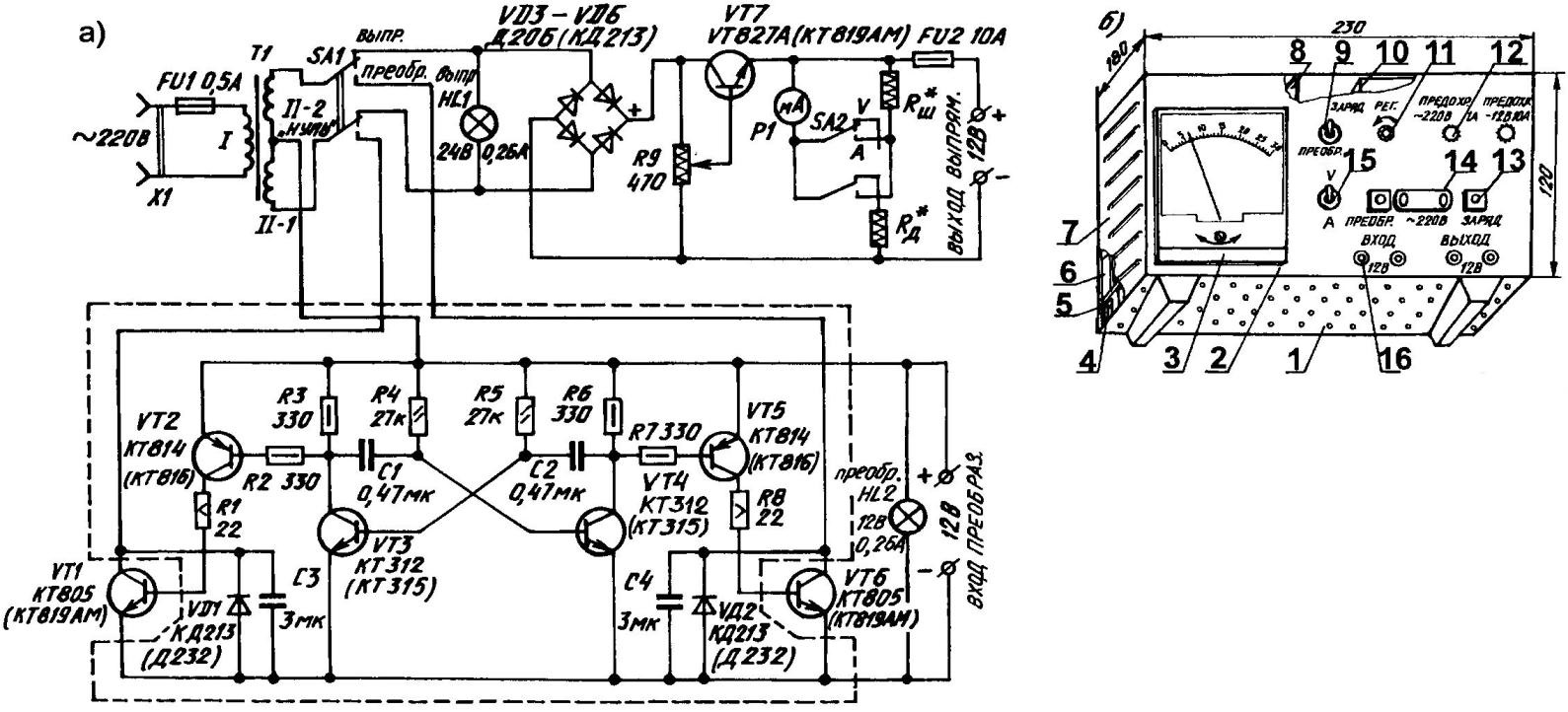
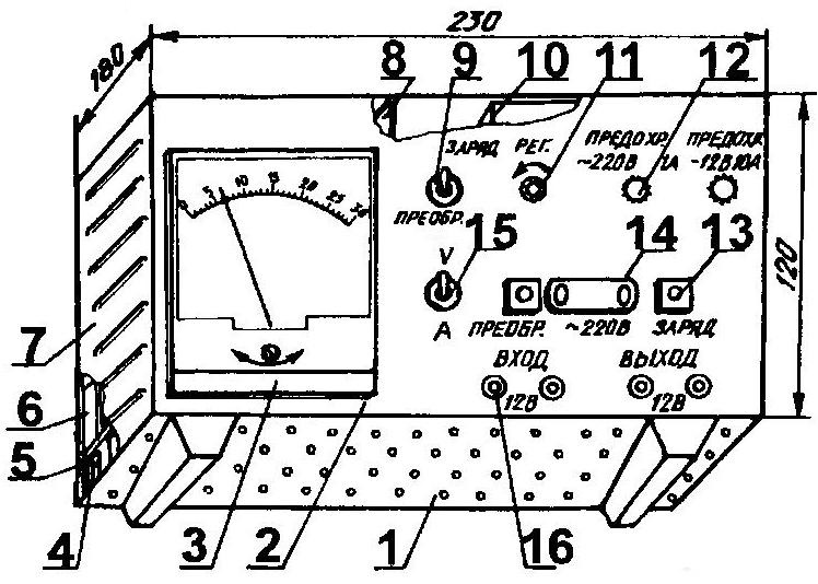
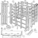
A circuit diagram of a Converter-universal (a) and a device (b):
1 — base-tray base; 2— front panel; 3 — measuring head of the gauge; 4 — insulating sleeve (number and size at the place of installation); 5 — chassis “angled” profile, with rear wall on which are mounted radiators for cooling the semiconductor valves and the transistor VT7; 6 — cooling radiators transistors VT1 and VT6; 7 — casing with ventilation slits; 8 — PCB generator subunit; 9— switch kind of works; 10 — transformer; 11 — knob of the rectifier; 12 — the guard (2 PCs); 13 — the indicator light (2); 14 — socket; 15 — the switch of the switching device with a measuring voltage measuring current; 16— terminal (4 PCs)
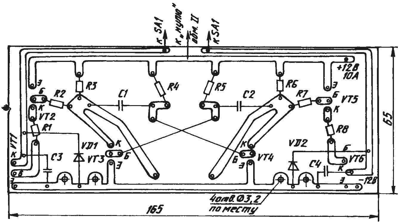
PCB generator subunit
When using the device for producing a rectified low voltage (AC 220V) is detached from the terminal ENTRANCE CONVERSION. 12 To translate the switch SA1 is kind to the CHARGE. Socket ~220 V is connected to a household outlet, and the load to the terminals of the OUTPUT bridge rectification..
As a result we have already discussed earlier the transformer in the secondary coil (series-connected II-1 and II-2) which is about a 20-volt voltage, and gate bridge. However, straighten the voltage supplied to the load immediately, but after the regulator transistor VT7 with a wire potentiometer REG. and the fuse FU2, designed for 10 A. in addition, the output electrical device-coil system that converts to incremental resistance connected toggle switch SA2 from the ammeter (position a) to the voltmeter (position V). LH1 lamp serves for indication of supply voltage to the bridge rectifier VDЗ — VD4.
Due to the fact that the device was conceived as a rectifier for battery charging or as a secondary source to power household appliances with power up to 100 W, having in its composition noise filters, special measures for elimination of background and of the pulsations of the rectified voltage was not provided. However, if you want “smoothness” and you’ll get 12 In it is possible to increase the connection parallel to the load capacitor bolsaescola.
Well, particularly fastidious users, it is recommended to Supplement the electronic “push-pull” more perfect filter. In particular, to equip the collected design one or two capacitive-throttle smoothing cells, functioning, electrical parameters and installation details which were described in the journal “modelist-Konstruktor” No. 11, 1999, the benefit of a place to put all of the elements of such a low frequency filter the device has.
Now the parts necessary to assemble the structure the Transformer is self-made, using widely known and available magnetic TBS 3-0,173. The winding of I contains 1290 turns of wire PETV-0,44. Consequently, II-1 and II-2 are the same. In each of them — for 73 turns of wire PETV diameter of 1.7 mm.
Homemade and shunt Rш additional resistance to the electrical device. Wound them from konstantinovoj or equivalent resistant of the wire diameter and the required number of turns specified in the setup process. But the very measuring head of the device ready to take (for example, M42100, the scale of which will graduate in A and V).
Resistors, capacitors, signal lamp, and semiconductor devices is also not one of the expensive. Basic data that should guide the choice indicated on the wiring diagram.
As a “mnogomernyh” toggle suit domestic TV 1-4. Fuse holders —ДВП4-1, switch — socket- type VD. You will also need a standard heat sink for the diodes Д206 (KD213) and for power transistors КТ815А (КТ819АМ), as well as the installation details of the type of lights for warning lights with red (HL1) and green (HL2) filters.
The Assembly generator subunit (with the exception of the transistors VT1 and VT6), it is recommended to implement on the PCB of one-sided foil fiberglass dimensions 165x65x1,5 mm. Mount, as wall mounting the rest of the entire device on the chassis of sheet steel, bent in the form of an “angled” profile 174×110 mm high rear wall which is used for the radiators cooling the power semiconductor devices (diode valves VD3 — VD6 and the transistor VT7), farmed out. To steel pallet having ventilation openings, the chassis is mounted with M3 screws and insulating bushings height of 15-20 mm. the faceplate of the PCB thickness of 4 mm, all the inscriptions engraved on it (you can run the ink). The casing is metal, from the same sheet of 1 mm thick steel with ventilation notchings on the sides.
GALEEV E., M. A., Ulyanovsk
Recommend to read
 FOLDING GYM CLASS
A large army of fans daily sits down to the TV screens to watch fights nimble, hardy, courageous. And among viewers — its most direct and most react violently to stressful events... RAM INSTEAD OF ROM
Debugging any program of the microprocessor, it is necessary many times to write and erase information in the chips ROM КР573РФ5 (РФ5). However, the online those is very limited. In the...
