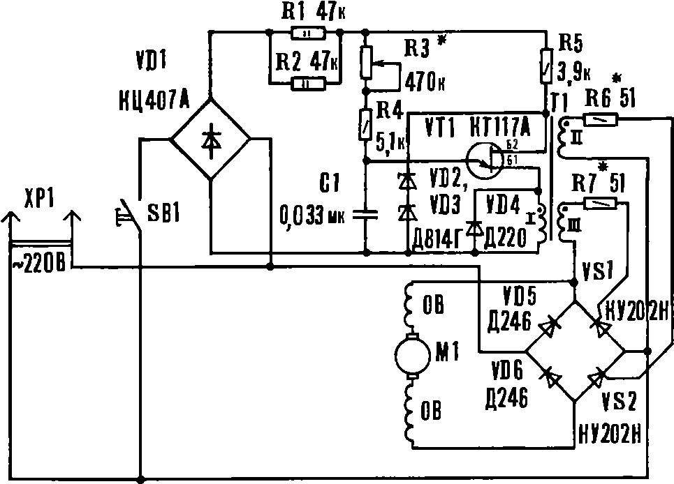
Input VT1 included integrating chain R3R4C1. At the beginning of each half cycle begins the charging process of the capacitor C1, and the voltage across it increases until the opening of the transistor, whereupon C1 is discharged to the primary winding of pulse transformer T1. When VT1 is closed, the circuits of the secondary winding T1 a pulse of control current that opens trinistor VS1, VS2. They turned off at the time of passage of the supply voltage through zero. Changing with the variable resistor R2, the charging time of the capacitor, set the interval during which the thyristors are opened, and thus supplied to the motor power. The faster C1 is charged, the earlier be opened thyristors and the higher the rotational speed of the rotor.
Zener diodes VD2, VD3 limit the voltage on the transistor.
Circuit Board made of foil fiberglass (see figure). Resistors R1, R2, diode VD4, and the wires to R3 and SB1 located on the reverse side of the Board, so in their places of connection, you must install the caps.
The circuit Board controller with the layout of the elements.
Pulse transformer T1 is wound on iron 1116Х8 (from matching transformer radio “Alpinist”). All three contain winding 300 turns of wire sew-1 is 0.15. Special attention should be paid to the mutual insulation of the windings. Their insights made stranded mounting wire. Fix the transformer with the help of made of tinplate, clips, pulls the core. You can use and industrial pulse transformer of suitable size.
To place a variable resistor R3 in the handle of electric drill, it is necessary to replace the stock switch to other, smaller (see Fig.).
The base is made of steel sheet with a thickness of 2 mm. Into the holes from the back side of the base are inserted and clench the stops that are used to mount the switch in the handle drill. On the inner side of the right half of the handle has three recesses Ø 4 mm under the stops of the regular switch. The base of the new switch with their lugs inserted in the holes and pressed the left half of the handle of the drill. Position the two end stops is determined by the place that the trigger switch was located and moved just as well as before the alteration. To the base attach microcopy KM1-1 and fasten screw M3 bracket. Latest with axis Ø 3 mm holding the trigger, which is translated in the initial state of the pusher with the spring. Spring, trigger, and axis – from the regular switch. The remaining parts are made of steel St3.
Switch:
1 — spring, 2 — pusher 3 — base, 4 — microcopy KM1-1, 5 — trigger, 6 — axis, 7 — bracket 8 — M3 screw, 9 — nut M8, 10 — stops.
Now in the formed in the handle cavity set variable resistor R3. To do this, in the left half of the handle, where there is a lock button under it, drill a corresponding hole in such a position that the regulator handle does not interfere when working with the drill and it was easy to rotate with your thumb.
To the body of the drill are mounted on short stands, with the glass fibre laminate washers (2 mm thick, 6 mm in diameter) and the long struts attached fee. To the long racks, in turn, the two M3 screws holding the rear cover of the drilling machine (see Fig.).
Mount the controller Board on the body of the drill:
1 — drill 2 — short stand, 3 — puck, 4 — long bar, 5 — circuit Board. In brackets shown the measurements for the stand 4.
The establishment of the regulator is reduced to the selection of the values of resistors R6 and R7. The setting is produced with an oscilloscope or voltmeter. The output of the inverter is connected an active load (e.g. the incandescent bulb of 60-100 watts). Resistors R6 and R7 are replaced by variables, and the load is connected to the oscilloscope or voltmeter. Changing the value of R6 and R7, achieve the same opening angle of the SCRs when R3=0 or the maximum voltmeter readings. The value of R3 is chosen such that at its maximum value at the output of the regulator voltage was about 10 V. the Controller can be collected in a separate unit-adaptor, plug straight into the socket. Then it can be used as a universal power regulator, feeding through it a soldering iron, lighting etc.
A. TRETIAK, Ordzhonikidze, North Ossetian ASSR
Recommend to read SPARK WITHOUT THE “WHIMS” Motorists made electronic blocks of ignition, as a rule, according to the classical scheme consisting of a high voltage source, a storage capacitor and a thyristor key. However, such... THE CONDUCTOR-TELESCOPE Of tubes of different diameter, tightly placed one on another, you can build a jig for drilling end holes in cylindrical rods of various cross sections. For the outer bushings are better... 
 Electric hand drill machine (or drill) there are many home craftsmen. But its opportunities will be wider if it is to provide a speed controller. In this case, the tool, in addition to its direct purpose, can be used as a screwdriver, and as a machine for winding coils. In particular, the design of the boring machine of IE-1019А allows you to embed an electronic controller in her butt — in the place where is located the entrance of the condenser, and the start button and variable resistor to set the handle of the tool.