
 In large apartments and private homes in the evening and at night it is difficult to follow the dark corridors or staircases to the touch to find the button and turn the lighting.
There’s another alternative — buy a standalone lamps soft light — can be installed in any convenient place at the discretion of the owner.
However, in addition to unconditional benefits, and such lamps have several significant drawbacks. First, they eat from batteries, which will eventually become useless. Secondly, as lighting elements in these devices involved incandescent bulbs, consuming (compared with LEDs) a relatively high current and having low efficiency, low life.
As an alternative, and more economical version of the proposed simple electronic device, scheme of which is shown in the figure. As the lighting elements it utilizes LEDs of high power, with the ability to adjust the brightness of the glow.
This pulsed low-voltage power regulator DC allows you to change the brightness of high power LEDs or the value of the current in the active load. Compared to lamps based on incandescent lamps, such a device devoid of their shortcomings, the service life of the LEDs corresponds to several tens of thousand hours, the possibility of smooth adjustment of power to the lighting device is intended for supply from Autonomous power sources (batteries, accumulators) and stationary stabilized power supply with voltage 6… 15 V. in addition, it is simple to manufacture, because it contains only one CMOS chip and assemble it even for a hobbyist with little experience. The use in the circuit of LEDs allows you to extend the capabilities of the device.
So, instead of defined in the arrangement diagram of LEDs, you can install LEDs of any color of illumination (blue, yellow, red, green, and others), and also, set even flashing LEDs — then this device can be used as alarm indication of any process, and the brightness is not inferior to the brightness of several miniature incandescent lamps (at voltage 6.3. ..13.5 V), resulting in hours of work.
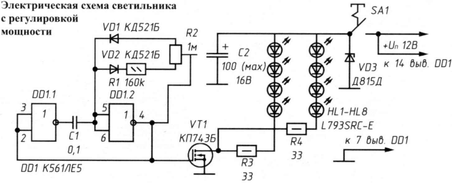
The electrical circuit of the lamp power adjustment
The device is easy to convert for smooth dimming in the car, as well as the brightness of the dashboard lights and many other suitable occasions. For this purpose it is necessary to include in the electrical circuit of the vehicle.
The principle of operation
In the device (see wiring diagram) applied chip К561ЛЕ5, both of which are included in the scheme of inverters. Each chip К561ЛЕ5 — four of the same item. The front and the cut of the output pulse does not depend on the shape of the input signal. On the elements DD1.1 and DD1.2 assembled generator of rectangular pulses with adjustable duty cycle.
The pulses output from the second item go to the gate of the power MOSFET VT1, in which the circuit through the limiting resistors RZ and R4 included load — two circuits with four LEDs HL1 — HL8. Transistor VT1 in the absence of the input signal has a large resistance (several mω) of the transition drain — source, so the current consumption of the device is negligible — only a few µa (when the LEDs are not lit) and can reach up to 200 mA (depending on the mode and type of applied power LEDs).
The transistor goes into saturation mode, when the output of the inverter DD1.2 are the pulses with the prevailing high level of stress. When the input transistor switch is dominated by rectangular pulses with a low level (this depends on the position of the variable resistor R2 for regulating the duty cycle), the transistor is closed, the current through the LEDs is reduced up to almost complete absence.
The brightness of the LEDs HL1 — HL8 changes depending on increase or decrease of the frequency of occurrence of positive peaks of the pulses at the exit of the element DD1.2. All unused inputs of the remaining two elements of the microcircuit DD1 (findings 9, 10, 12, 13) preferably combine with each other and connect to the “+” supply.
The transistor should be mounted on the heatsink — you will need it in case of prolonged use of the device in the on state (mode 24 hours).
Transistor switching occurs with an almost constant frequency of 330 Hz. With the help of variable resistor R2 (preferably to apply SPO-1БВ) duty cycle can be changed so that the power fed to the load varies from 5% to 95% of the limit value. The glow of the LEDs is soft, flicker is not noticeable.
Installation
Circuit Board to save time, had not been developed. The elements were fixed on the circuit Board. The findings were connected with jumper — wires MGTF section 0,6…0,8 mm.
Industrial luminaire housing (photo on the splash screen) with the controller in mounted in a convenient location and connect to the conductors from the stationary power source through a compact connector (for example, РП10-5).
The knob of the variable resistor needs to be able to change the brightness of the LEDs if necessary.
Networking device is not required. At the connection of outputs 1, 2, 4 chip DD1 oscilloscope to conveniently monitor the availability of pulses and by changing the position of the engine variable resistor R2 in their duty cycle.
Details
A field-effect transistor КП743Б can be replaced by КП743А, КП510 with any alphabetic index or foreign analogue— IRF511. All constant resistors — MLT-0,5.
During long-term operation of the device, the resistors will be heated to a temperature of 40…50°C. If you intend to work in 24 hours — it is better to replace more powerful, with a power dissipation of 1 watt.
The capacitor C1 is of type KM-6. Diodes VD1, VD2 can be replaced by KD521, KD522, Д311 and the same with any alphabetic index. Zener VDЗ serves as a protective element of overvoltage from a power source (for example, when installing the device in the car). In the above diagram, you can replace any other, providing a voltage of 12… 13 In a runoff at least 25 mA, and if you use the device in the apartment powered by a stabilized current source — VDЗ should be deleted from the scheme altogether.
The oxide capacitor C2 filters the ripple voltage power source with low frequency. It can be any type (for example K50-29).
Instead of chips К561ЛЕ5 you can use the chip K561LA7 or К1564ТЛ2, K561LN2 with the schema changes of the last two because of the different Pinout of the findings.
Variable resistor R2 (except the recommended SPO-1БВ) can be type GPA-12, GPA-З0В and similar. It is desirable to have a linear characteristic of resistance changes of the letter “V” In the index.
LEDs also indicated in the diagram, it is permissible to replace the type of RS276-143 and similar. If indicated on the diagram LEDs (8 pieces) are too bright, their number without changing the values of the circuit can be cut — through under regulation is always possible to set the required power of the glow. Powerful LEDs L793RSС-E are intensity of 2.8 CD (Candela). It is not comparable with the strength of the glow once popular indicator led АЛ307БМ (no more than 10 millicandela), so the luminous flux and also because of the possibility of adjusting the luminous intensity, the proposed device, in my opinion, will be relevant in the future.
A. KASHKAROV, G. s a n t-P etersburg
Recommend to read
 APPLES INSTEAD OF… UNDERWEAR
Fans of Apple juice can offer simple to manufacture and does not require significant investment homemade juicer. It is made from an old washing machine. The factory extractor has low... CLOSURE TWO HOOK
Neat craftsman, working in his workshop, be sure to tie a safety apron — so as not to stain or damage clothing. And not to bother with a drawstring, it is better to attach to the apron...
