
 Efficient and reliable operation of electronic devices depends largely on the temperature regime of each individual circuit element, especially if they work for 24 hours a day. Temperature, in turn, depends on the power load and output (key) cascades of stability of supply voltage.
 Devices that require constant refrigeration, provide special small-sized fans — coolers. They do not allow this element to overheat and fail. They are installed on the computer processors, the chip system and graphics card, radiators of powerful audio amplifiers and other electronic components.
Overheating is a complex and highly integrated devices and entire electronic assemblies is fraught with not only the fault directly of those elements, but also the failure of “the chain” all of the circuit components.
But the fans happen to be deteriorating. Then the element or IC chip faces directly thermal break with all the ensuing consequences.
Is it possible to control the operation of the fan? It turns out that you can.
The idea to design this simple pattern came to me during the repair of the car. In such domestic products of the automotive industry, as VAZ-21063 minibus “Sobol” GAZ 2752 and the other the radiator cooling fan does not work continuously, but is activated when the liquid in the radiator is heated above +87°C. For that “meets” temperature sensor, coolant, installed directly to the vehicle radiator.
Unfortunately, this sensor often fails (from the practice of the author), and therefore forced ventilation is not included. In the end, the liquid boils — the car has to stop and repair. The simplest solution in this case (in the field, when in whatever was necessary to drive to the auto parts store, auto service or to the home) — to close the contacts of the sensor coolant temperature (modeling the situation when the relay temperature sensor will turn on the cooling fan).
The analogy with cars here is not accidental. After all, in electronics overheating of the elements as undesirable and dangerous as in a car. So, you need a sensor, signaling the failure of the fans and informing the user about it. The author offers a very simple device in relation to the engines coolers with mains-powered DC voltage of 12 V, the electrical diagram is presented in Fig.
The motor M1 is turned on (with correct polarity) through a current limiting resistor R1. When power is applied to the device at the point of connection of the lower (scheme) the output of the motor is V1 and the resistor R1, pulsation DC voltage with an amplitude of 0.3 — 0.6 V (depending on the build quality of the motor). This pulsing (when the electric motor) the voltage is complex and chaotic form. The separation of the capacitor C1 does not pass the DC component of the voltage, so the base of the transistor VT1 is supplied only the variable component of the control signal. During normal operation of the motor M1 AC voltage in the base of the transistor VT1 periodically opens this transistor, not allowing to charge the capacitor C2 and to open the field VT2 transistor. Non-polar capacitor C2 performs the device is another important role. It stabilizes voltage “source — gate” field-effect transistor VT2, thereby providing the soft sound of the cap HA1.
When you stop the motor cooler (for any reason: break of the internal circuit of the winding, the contact between the blades foreign object, etc.) of the ripple voltage in the base of the transistor VT1 is missing. The transistor is closed (this also contributes to shunt resistor R2). A field-effect transistor VT2 at this point is open as it receives a control voltage through resistor R3. As soon as the voltage at the gate of VT2 reaches 3 V, this field effect transistor will be opened and will sound the capsule with a built-in sound frequency generator HA1.
The sound generator has a fairly loud sound that can be heard for distances up to 15 m in the room. Audible alarm will remain on until the unit is de-energized or until a new working motor cooler (for example, after the removal of his blades, foreign object). The switch SB1 device brings an extra flavor: when the closure of the contacts SB1, the motor M1 operates in full force, while another group of contacts opens the power circuit of the sound generator.
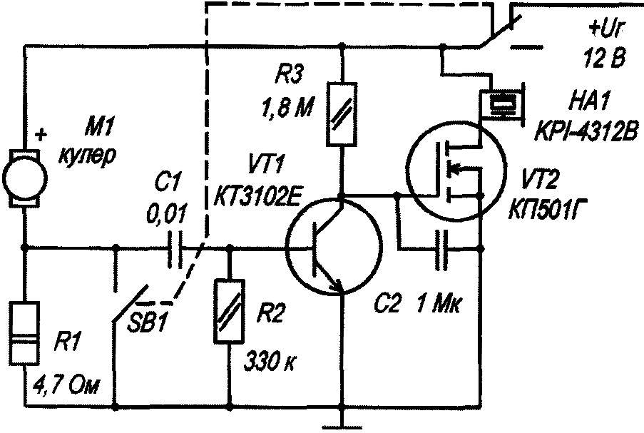
Schematic diagram of the rotation sensor of the cooler.
The establishment
The device is in adjustment not needed and begins to work immediately after switching on. When the power source voltage of 24 V (in accordance with the controlled electric motor), may have to pick up (adjust) the sensitivity of the device, which depends on the elements C1, R1. If you increase the capacitance of the capacitor C1 and resistance of resistor R1 increases the sensitivity, and to reduce it by reducing the resistance of the resistor R2.
Details
In the example as applied cooler fan to cool the computer case, designed for constant voltage of 12 V and current of 0.1 A.
The same method can be used to control the operation of other low-power DC motors with an applied voltage of 12 V. for Example, it can be electric type DOT-301, DKM-1 (0.12 A), 4ДКС-8 and others. When the rotation control of electric motors with a rated voltage of 24 V, for example, DKC-16 (24 V), need to replace the transistors VT1, VT2 other, in accordance with the reference data.
The switch SB1 type MT3-9-2 (dual microswitch, in the form of a toggle switch). If a direct “manual” motor operation is not required, this switch from the circuit rule.
Capacitor C1 — the type of MBM, K10-17 and similar. Non-polar capacitor C2 — type K76-P2 or similar. Instead of transistors КТ3102Е you can apply КТ3102Б — КТ3102Д. Field effect transistor — type КП501 with any alphabetic index or foreign equivalent ZVN2120. Fixed resistors type MLT. HA1 earpiece with built-in AF generator can be replaced by any other similar, designed for a voltage of 10 — 15 V. If the rated voltage of the motor 24 In the capsule, replace the corresponding, designed for this voltage.
The scope of the sensor
The prospect of using the recommended sensor is not limited to electronic equipment. For example, greater benefits he can bring in the aquarium when it is required to control the normal operation of the pump-pump, because its working area often (no exaggeration) crawl of a snail, whereupon the pump ceases to work, the aeration is stopped, which can lead to tragic consequences and ruin lives in the aquarium.
This is only one, but quite telling example, and they can cause a lot.
A. KASHKAROV, St. Petersburg
Recommend to read
 “FIFTEEN PUZZLE” ON THE WATER
Water motorcycles, or scooters, are very popular among water motor sports enthusiasts and athletes. This type of transport has expanded the range of watercraft, contributes to the... Off-road Smart ForTwo
Do you know, sometimes the craziest ideas are born not from an excess of free time, but from the desire to prove to yourself that the impossible is actually quite real. Imagine this: there...
