
 The availability of modern element base used in television remote controls (remote control), allows you to create a simple counter connected to the receiving side of the computer LPT port, adapting all this to count, such as boxes with finished products on the conveyor.
Indeed, the transmitters and receivers are infrared (IR) radiation used in remote control systems in modern TV sets and VCRs made in the form of a monolithic mikroblogov work on the removal of up to 6 (sometimes to 8) m! Such high sensitivity is achieved largely due to pulsed signal transmission and digital filtering low-frequency interference. And the cost of such devices is quite affordable for most.
So why most do not use that purchase equipment do a slightly different quality when the line of the infrared barrier is crossed by, say, finished products, will begin to operate in pulsed mode, and the counting of the above boxes will be carried out by integrating the received IR signal? After all, it is quite acceptable for good-quality technical solutions situation: the pulses are received — so the barrier is; if there is a constant signal, the barrier is breached. And feature integration can successfully perform a diode and a capacitor.
But the impulse transmission mode creates a specific obstacle. With a smooth crossing an infrared barrier duty cycle increases and gradually the output signal from the photodetector becomes constant.
It is proposed to eliminate the edge the interference is to use a controlled oscillator (for example, on the chip K561LA7). Its frequency greatly exceeds the frequency transmission over infrared channel.
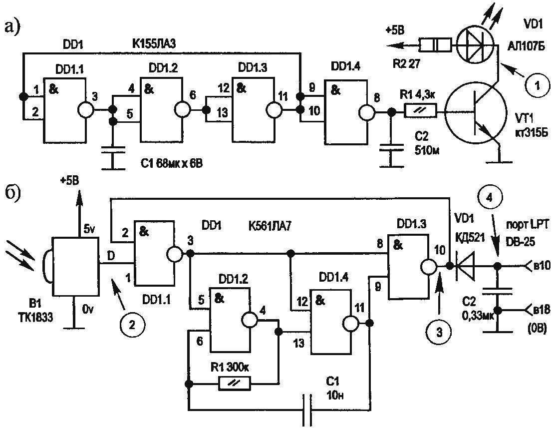
Circuit diagram of IR transmitter (a) and IR receiver (b) using the remote control from TV or VCR (video player)
I have developed a modification of the circuit diagram of the transmitter is designed so that the generator can output only the pulses with its frequency without changing of duty cycle. So, eliminating the passing of edge noise on the diode and the capacitor of the integrating circuit. The selected frequency controlled transmitter and IR generator allow you to count crossing an infrared barrier at 10 — 15 MS, which is sufficient for most possible applications of this device.
As rosary algorithm and the IR receiver, schematic diagram of which is presented below. And next are the waveforms of signals taken at points of fotosdechicas.
In addition to the previously mentioned IC K155LA3, in the transmitter includes the switching transistor with the emitter — led АЛ107Б. Pulse frequency is determined by the capacitor C1 in the feedback circuit. C2 at the input of the transistor VT1 filters high frequency switching noise.
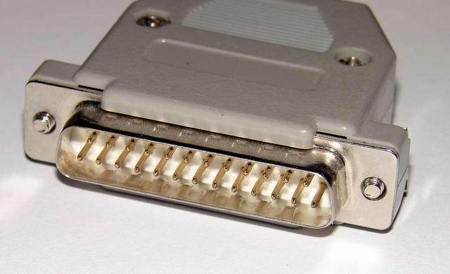
The photodetector Q1 is imported, the type ТК1833, СР107 or at least a worthy equivalent. All three bring such a semiconductor device are enclosed in a metal housing. The common electrode (vyv.0v), usually the most extreme, should be connected with the very case. However, the location of the battery + +5v and battery + D of the photodetector may vary from the model. To clarify the Pinout use the oscilloscope.
Filing for one of these two conclusions the “positive” voltage, the other (not General, which, of course, must be connected to the minus power source) connect to the input of the oscilloscope. Point the do any radiation on the photodetector and control the output signal. If you can see the pulses, the Pinout is identified correctly. Otherwise, definitely have another option.
If at hand there is no oscilloscope, use to verify the Pinout of the sensor zvonkova a piezoelectric transducer SN-1. When properly connected, it will emit a squeak that corresponds to the fundamental frequency of the IR signals. In addition, make sure the receiver and transmitter on the same line. With a large ambient light on the photodetector install blend (light visor).
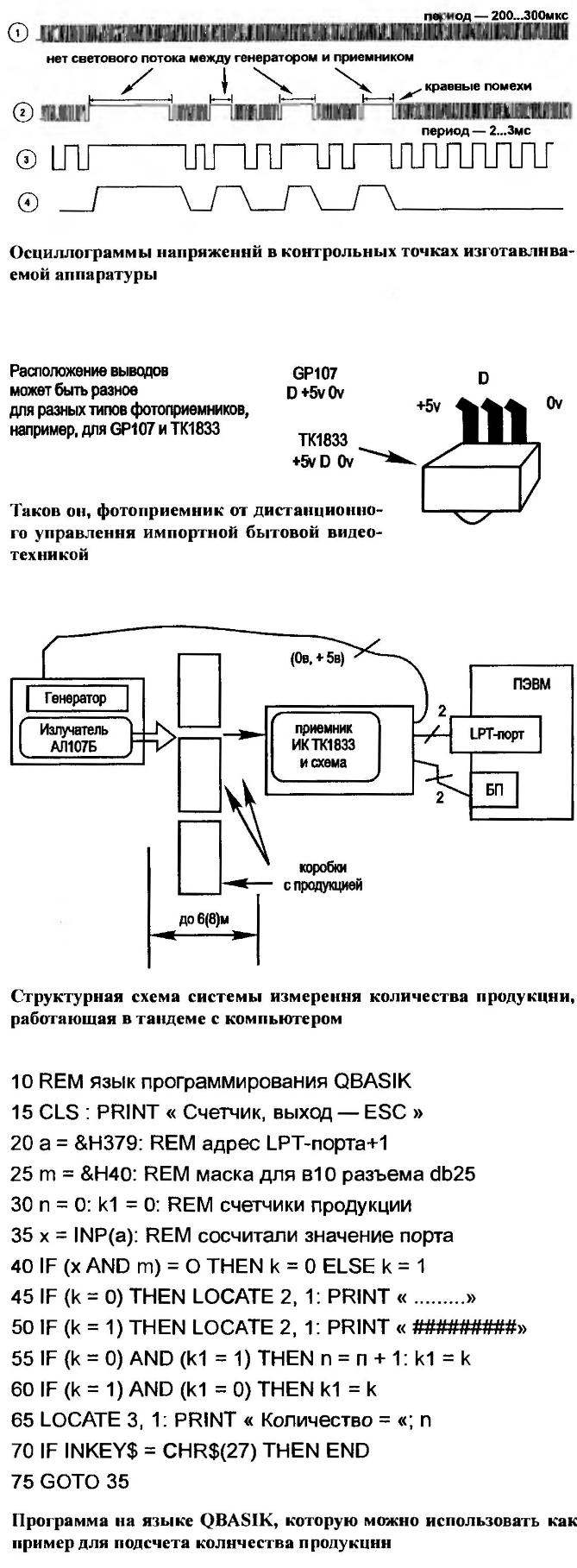
This counter is convenient to immediately connect to the computer using, for example, a LPT port, and in accordance with the program written in the language of QBASIK, to get to work. If necessary, you can quickly and easily test the program: it is enough to short the pin 10 of the DB-25 connector on the housing.
Software has been developed to counter data is too large to reproduce in the magazine. But it can at any time download for FREE from author page www.irs.ru/~shabr in the Internet.
A. SHARONOV, Novosibirsk, Russia
Recommend to read
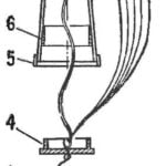 RECOVERY SYSTEM MODEL ROCKETS
How to ensure reliable and trouble-free fit of a model rocket? The solution to this technical problems struggling for many modelers. According to statistics, more than half of the models... MAGNET AGAINST THE WIND
To open window the window is not closed under the impulse of the wind, it is easy to establish a kind of brake, which would not allow it to close, and left at least a crack. On the...
