Figure 1 is a circuit diagram of the multivibrator on chip КР1006ВИ1 included in the oscillatory regime, and a simple oscillator with adjustable parameters of output pulses in a wide range (i.e. the generator of the universal destination – with a little refinement of the output stage, it is effectively used as high-voltage Converter for flash SEF-1).
Fig. 1. The electrical circuit of the multivibrator on chip КР1006ВИ1 included in the oscillatory regime
Consider the operation of the multivibrator. When power is applied to the circuit elements, the capacitor C1 has a very low resistance to electric current and begins to charge through resistors R1, R2 from the power source. For the first time on the trigger input (pins 2 and 6 DA1) there is a negative pulse, and the output of the chip (pin 3) is set to logic high. The voltage charging the capacitor C1 increases exponentially with a time constant t=RC, where R is the sum of resistances R1 and R2. When the voltage on the plates of the capacitor C1 reaches 2/3 of the supply voltage, the internal comparator resets the trigger circuit to its initial state and trigger, in turn, quickly discharges the capacitor C1, and switches the output stage to a state with a low voltage level. Thus, periodic charging of the capacitor C1 through the circuit resistances R1R2, and the discharge through resistor R3. It allows you to adjust the duty cycle within a wide range, by setting the ratio between the resistances of the resistors R1 and R2. Timing resistors R2 and R3 determine the parameters of the pulse generator and its frequency within wide limits: R2 adjusts the pulse packet (the smaller the resistance, the shorter the tutu, down to single pulses), R3 regulates the pause between pulses from 0.5 to 30 s. the parameters of the frequency of the pulse also depend on the capacity of the capacitor C1, which can be applied to hundreds of UF. In this mode, the voltage on the plates of the capacitor C1 is changed from 1/4 to 2/3 of the voltage of the power supply. The charge rate of the capacitor and the switching threshold of the internal comparator is directly proportional to the supply voltage, therefore the duration of the output pulse from the voltage practically does not depend. The timer output switches КР1006ВИ1, dramatically changing the voltage at terminal 3 and DA1. Pin 5 of the chip need to be left free or connected to GND via a capacitor of the type KM, a capacitance of 0.1 UF. In this scheme, it does not matter.
The oxide capacitor C3 smooths the ripple voltage from the power source. The output current of the generator on the chip КР1006ВИ1 (output 3 DA1) does not exceed 250 mA, for many Amateur designs is enough. To connect the console directly to the pulse transformer of the flash. However, to control the high-voltage pulse load the necessary Converter with galvanic isolation (scheme in Fig. 2) – he’ll need for “taming” the other (also reviewed) types of flashbulbs.
The transducer cascade is implemented on the field VT1 transistor, in the circuit of the source of which included the winding of the boosting transformer T1 in the flash. For additional protection of the output stage in circuit with the transformer applied supressor (protective Zener diode) from КС515 with any alphabetic index. Protective Zener diode must have a voltage stabilizing at least 3/4 Usup.
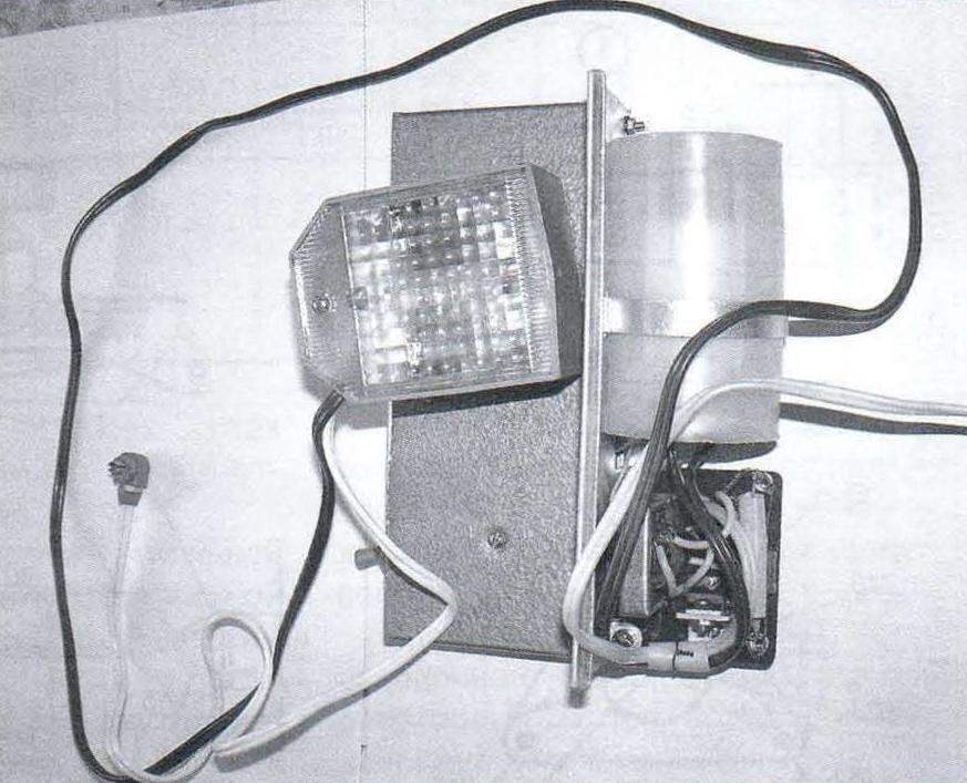
Chip at work may become warm to 30° – 40°C. the battery of the device can be stand-alone (battery type “Crown” with a step-up voltage Converter for operation of the flash lamp) and a stationary power supply with stabilized voltage of 6 to 15 V.
About the details. A field-effect transistor VT1 can be replaced by IRF640, IRF511, IRF720. Variable resistors R2, R3 with linear characteristic change of the resistance – multi, for example, SP5-1ВБ. Instead of electrolytic capacitor C3 will fit the type K50-29 or similar. Fixed resistors type MLT-025, a non-polar capacitors – type KM.
Practical application of the combined device may be different. Except for the first one that comes to the mind of a young man, to set him on the dance floor in the strobe (pulse frequency multivibrator in this case, select 1 to 10 Hz), there are other options. For example, I now used the device for remote indication normal operation alarm of a village house. The fact that my farm is separated from the village by a few miles. Message — the forest road. But due to the fact that it is located on the hill of the village seen the very estate. But of course, it is difficult to see if there is extraneous. And this is important because most of the time I live in the city, many kilometers from the farm. But periodic bright flashes (repetition rate 0.1 Hz) of the flash lamp IFK-120, together with the reflector aimed in the direction of the nearest houses, will inform about the situation when someone climb in the house – the alarm is triggered, guided me via cell phone (at a distance), the flash light will stop blinking — this will serve as a Wake-up call.
Fig. 2. The electrical circuit of the output stage of the voltage Converter
After installation and connection of the considered devices only have to negotiate with local residents that they were looking towards my farm. Their main task, of course, is not to pinpoint the time of the alarm (that I spotted immediately, as well as local police that will call with a cell phone installed in the estate and performing the role of “remote alert”) and to trace and try to remember the identity of those “good” people that will soon follow on foot or by car from my village. A matter of law enforcement.
Day and especially at night, flash IFK-120 are clearly visible in the very far distance, which can be used in other cases when you need a remote alarm device.
Another option is the use of hybrid designs is the protective function of the house owners. Flash is in the hallway (right after the front door) reflector to the output, the power supply to the device is via an ordinary wall switch. If the logged in visitor is, to put it mildly, unwelcomed, it is easy, by pressing the main switch to work the flash that is included in the strobe mode. He will be paralyzed in action in a contactless manner (his life is not in danger).
The device can be adopted not only in country houses, but also in urban apartments. And can be and more extravagant options. It’s all in the imagination and its skillful implementation.
A. KASHKAROV, G. s a n t-P etersburg
Recommend to read “SKYSCRAPER” CHAMPION All conscious life Vladimir Menshikov associated with the sky. In his childhood he built flying model airplanes. Hence the choice of a profession. And as a matter of course, flying... Brake light controller A vehicle’s electrical system can be supplemented with a device whose schematic and wiring are within reach of even a beginner. This device is a controller whose value is clear: its status... 
 In my opinion, the most effective seem to be those developments that do not need to “up from zero”: we will focus on improving ready-made industrial electronic devices on their own. The result is a very modern functional design, one of which I bring to your attention. This is an additional node to industrial flash SEF-1 produced once the millions of “copies”.