 (Continued. Beginning in №1,2,3 ‘2005)
 Instruments based on radiopriemnye. Audio amplifier
Audio amplifier (uzch) is formed from the staff of the cascades on transistors VT7 — VT10 and recycled stage transistor VT6, which in the standard version is a III cascade Ombudsman and also serves as a pre-cascade uzch when connecting a piezoelectric pickup.
From the base circuit /T6 deleted the kom resistor 590, connected to the socket “Star”. Nest “Star” through the capacitor 10,0×10 connects to the base of VT6. A 390 pF capacitor from the drive circuit (L39) is removed and in its place put the jumper. Shunt capacitor of 0.01 µf must be removed. Now the resistor is 3.9 ohms in the collector circuit VT6 will play the role of load. The collector VT6 is connected to a normally open contact switching group of staff.
Scheme I cascade uzch and switching it on regular uzch shown in figure 15.
Thus, GSC starts working when you remove the plug from a socket “Fi”. With the introduction of both forks in sockets “Star” switch group connects to the input of the staff uzch I cascade and nest “Star” can apply an external low-frequency signal. Band of amplified frequencies is significantly higher than in normal execution. The maximum double amplitude of the input signal to obtain an undistorted output is 80 mV in the frequency range 350 — 10 000 Hz. Frequency response full uzch shown in Fig. 16. Gain uzch is 40 units.
Sound generator probe
Sound generator-a probe can create by breaking the chain PIC at the entrance GSC. Right middle compartment (under 9-pin tube panel) is set 5-pin connector from the VCR.
The wire connecting the leg No. 9 lamp panel with the normally closed contact of the regular switch “Star”, he otpisyvaetsya and connected to the leg No. 4 of the connector, and to the leg No. 5 is soldered to the wire coming to the normally-closed contact. To cable (return) the fork is soldered a two-core wire with probes on the ends. The latter preferred to make the collet pencils, inserting them instead of the stylus cuts a pointed copper wire in diameter 2 — 2,5 mm soldered thereto by wires placed through the casing of the pencil. If you got the pencils under the stylus with a diameter of 4-4,5 mm, the probes can be made of copper wire of appropriate diameter, which if necessary can be put on clips of type “crocodile”.
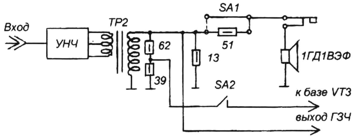
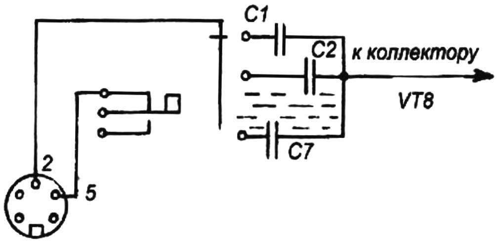
Circuit switching the output signal GSC
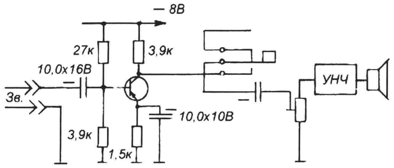
The scheme of the first cascade uzch switched
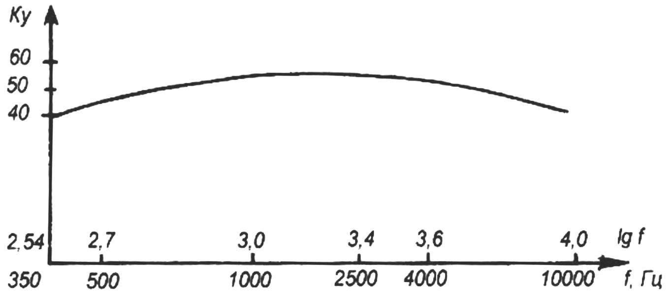
Frequency response full uzch
Connection diagram of the probe shown in figure 17.
Aperiodic receiver
Aperiodic receiver (AP) designed for independent study of the cascades of the device when passing the AM RF signal. Thus the AP allows you to replace a subsequent cascades when working with signals with amplitude of 0.1 — 1 V. AP is formed from the RF probe and full uzch. Current input RF probe RF AM signal is detected and selected at the output of the RF probe AF-signal is amplified uzch and tapped on the speaker. With a weak external signal (amplitude less than 1 mV) signal is applied to the input I of the Ombudsman, and the RF probe is connected to the output of the RF amplifier II. The input circuits must be disconnected.
The main characteristics of AP: the band of the studied RF-signal of 100 kHz — 30 MHz; the amplitude of the signal is 0.1 — 1000 mV; bandwidth of AM signal — 100 — 5000 Hz; the shape of the AM signal — a sine wave pulse. The amplification factor AP is virtually identical to Ku for RIO plus Ku uzch and ranges from 8,000 to 240.
Bridge mixer
In contrast to the classical scheme based on the revised cascade radio bridge mixer easier though, because not involved for additional details and uses already constructed blocks. The bridge mixer tap is made from the AP, RF probe and full uzch.
The output Jack of the HS with two-pole plug is connected with the output socket I, the Ombudsman, in the output socket II of the Ombudsman inserted plug direct wire. When you enable the TOS for the 27K resistor connected to the output socket of the TOS will mix the signals of the HS and the external RF generator of the test when serving his signal on the input socket I RF amplifier.
At close values of the frequencies of the two generators on the resistor 27 ohms will be allocated to the signal beating, which is amplified by the RF amplifier cascade II and through the straight wire from the output of the RF amplifier II will be submitted for regular listening via the loudspeaker on the regular nest”, This” full uzch.
Connection diagram connector for chopov
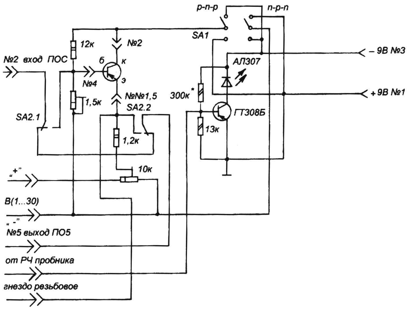
Diagram of the universal consoles (the resistor values are allocated with the * icon, selected during setup: SA1 —in p-n-p, SA-2 — in position GSC)
At equality of frequencies of the two generators signal beating will disappear (zero runout). The frequency of the oscillation of the test oscillator is read from the dial of a radio (when converted contours of the local oscillator).
The sensitivity of the bridge-mixer in the perception of zero beating by ear using the standard loudspeaker is an average of tens of microvolts across the frequency range.
A radio of direct amplification
Redesigned cascades allow to implement the scheme of the receiver of direct amplification. The implementation of this scheme is done by the following manipulations. Contour specified range via a switch SA1 is connected to the input I of the RF amplifier, the RF amplifier output II connects the RF probe.
Weekend plug RF probe is inserted into the socket of the regular “Star” on the back of the radio. In this case, one plug is grounded, the second switches switching the regular group in a position where the signal from the RF probe supplied to the base of transistor VT6, and the collector VT6 is connected to the base of VT7 — that makes complete uzch. Switch SA1 is translated up (full connection of the loudspeaker to the output winding of the transformer TP2).
In LW and MW reception is conducted on regular magnetic antenna on the HF-bands, loud-speaker reception is possible with a well made external antenna and ground.
Universal console
The universal console is intended to determine the integrity of semiconductor devices — diodes, LEDs, SCRs, Zener diodes, varicap diodes, bipolar transistors and their basic parameters. Using the universal consoles you can measure the DC voltage and control the presence and level of the output voltage of the various RF stages.
Universal console is a separate unit and connects to the instrument set the short cable of five wires. The console contains two voltage divider with a variable divide ratios and together with the tested semiconductor devices forms a coherent measurement circuit when measuring the parameters of the diodes, LEDs and triacs, or a parametric stabilizer when testing Zener diode, or an amplifier circuit with common collector (OC) when testing transistors.
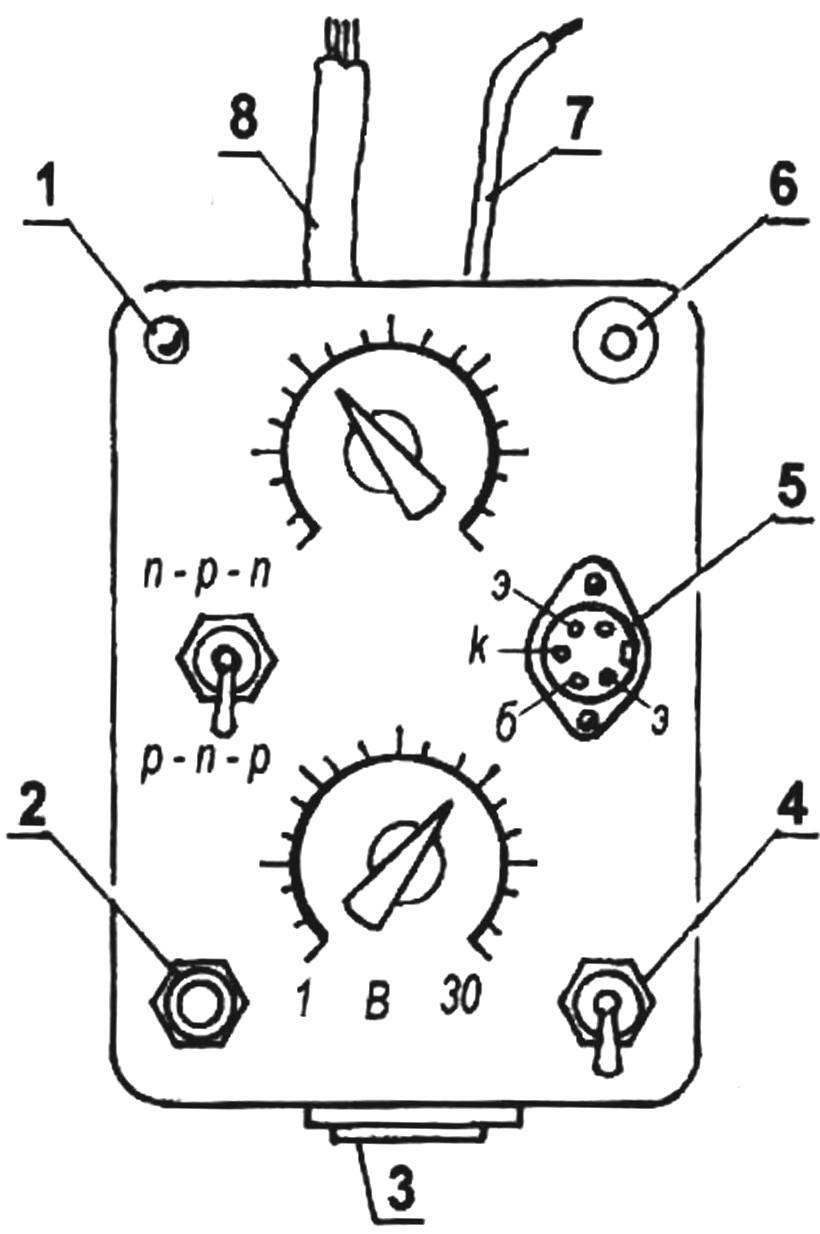
The construction of the universal consoles:
1 — led; 2 — button switch-voltage Zener diodes; 3 — terminal probes; 4 — switch off the console; 5 — panel connections of the transistors; 6 — threaded socket; 7 — cable to the RF probe; 8 — five-core cable
One of the voltage dividers included in the base circuit of the test transistor, the second in the emitter circuit. Point base and emitter is included in the circuit PIC GSC (includes the probe in the generator mode of the probe) using two wires. Three wire on the console is powered — shared “+” , — 9 and — 15 V. the Leads are combined in cable.
As the scheme is OK with not reverses the phase of the moved audio signal, the normal semiconductor device GSC will generate oscillations of audio frequency. If you start changing the voltage at its base, the greater the gain of the transistor, the higher voltage on the base of the transistor will occur generation. If you stabilize the voltage at the base of the transistor, changing voltage on the emitter, you can pick up this value with which the transistor is locked and generation will be missing. This allows us to use this console as a DC voltmeter.
Meter (indicator) output voltage RF is a single-stage voltage amplifier, high-frequency transistor of low power (ГТ308Б, П423, ГТ309Б, КТ361БГ, П416Б), in the circuit of the collector which led АЛ307. To the input of the amplifier is supplied either rectified voltage output from the RF probe (galvanic input) or AC signal of radio or audio frequencies via a capacitor. The amplifier used in the configuration of the complex and is used for indexing the RF oscillations of GS and HRU can be applied in all cases in determining the presence and level of the signal.
In the case that it is impossible to use the RF-samples-nick uzch, last working as GSC to modulate the TOS or HRU. In addition, the indicator in conjunction with RF probni-com can be used when configuring various radios and devices.
If necessary, the prefix turns off the switch SA2, the switching circuit PIC GSC with measuring circuits for direct connection (output and input uzch included directly). The power indicator remains: it is useful due to the fact that the indicator is used as an independent measuring unit.
With this prefix you can define as low-frequency and high-frequency transistors small, medium and large capacity, type p-n-p and n-p-n. Programmirovat the scale of resistors of 1.5 kω and 10 kω on the known values of the transistors and the test values of the applied voltage, can thus be measured In constant voltage.
The ends of the wires consoles soldered to the legs of the cable connector from the VCR. Connect cable connector to the instrument (right middle compartment) to which you have previously connected probes generator probes. Wire to power the console soldered to the legs: — 9 — to the leg No. 3 instrument connector +9 V — to the stem No. 1, the base of the test transistor to the leg No. 2 of the emitter to the leg number 5. Thus, the wires soldered to the legs of No. 2 and No. 5 instrument connector previously connected with the probes generator probes, now go to the entrance and exit consoles.
The console is going in a plastic housing. In the end drilled holes for output wires cable and wires for RF probe at the other end of the tape is set to 5-or 3-pin panel connector to connect the previously made probes generator probes now used to measure the voltage. Another 5-pin socket is mounted on the upper side of the housing for connection of the test transistor.
Connection powerful test of diodes and SCRs is carried out by means of a threaded socket with M6 thread. Through the opening in the top wall of the box threaded socket extends screw. Screw mounting petal placed and soldered to the socket “a” panel transistors. To connect the cathode of the SCR and the control element are made of two short conductor with clamp type “crocodile” on some ends and soldered plugs on the other ends for connecting to panels of transistors.
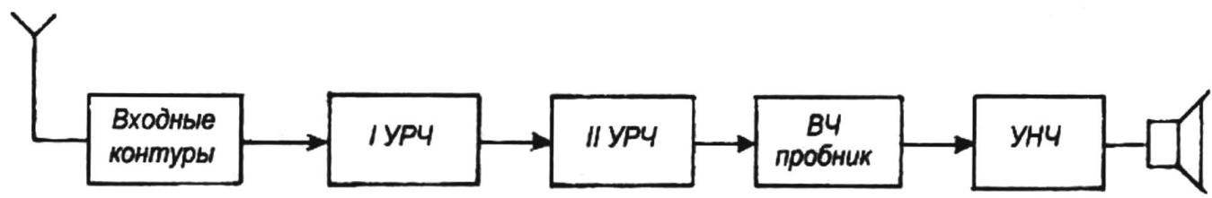
Connection diagram of blocks of the receiver of direct amplification
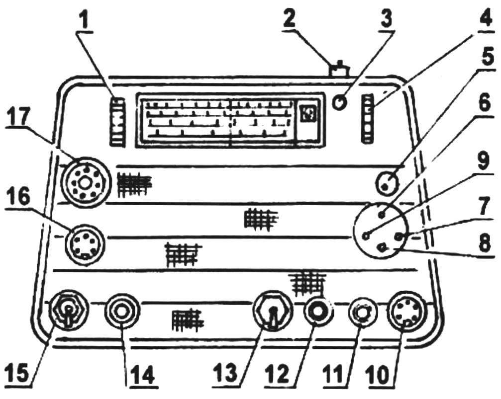
Appearance system:
1 — volume control; 2 — switch circuits; 3 — led; 4 — frequency tuning of GS; 5 — regulator output voltage HS; 6 — outlet GS; 7 — II the output of the RF amplifier; 8 — a output I RF amplifier; 9 — input RF amplifier; 10 — the power switch GS — HRU; 11 — housing (ground); 12 — output uzch; 13 — the switch of AM; 14 — HRU output; 15 — switch-speaker; 16 — connecting connector consoles; 17 — frequency switching GSC
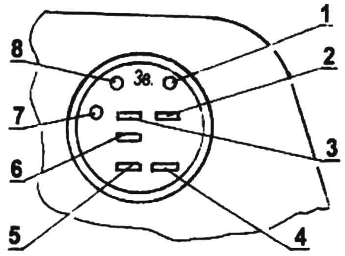
Modified regular socket on the back side of the receiver:
1 — housing and inclusion GSC; 2 — 15B; 3 — unused output: 4 — 9V, 5 — output +9V; 6 — turn off the loudspeaker; 7 — WA1; 8 — signal AF
With consoles you can test the integrity of any high-frequency and low-frequency diodes are small, average and big capacity (with current up to 10 A). On the front panel of the console removed the button SB1, the power is switched on, Zener diodes, and polarity switch power supply SA1. The design of the console shown in figure 20.
The definition of integrity and settings of all types of diodes, varactors, Zener diodes and SCRs conducted on HSC frequency equal to 100 Hz. The integrity of the transistors is determined at a frequency of 1000 Hz, the gain of the transistors In the frequency of 100 Hz. The measuring voltage is also at a frequency of 100 Hz. To measure voltage you must use a separate (model) transistor with a high V. If voltage measurement to apply a variety of transistors (different value), then the scale of the voltmeter will be off.
Describes methods of measuring the values of the gain of the transistors and voltages have very high accuracy, therefore they would name the methods of measurement and testing methods (mostly comparative) of the quantity.
Front and back panel
On the front panel through a hole of 6 mm in diameter, drilled between the window pointer ranges, and the handwheel settings, removed the indicator led indicating the on state of the complex. The led is soldered positive conclusion to the mounting lobe, fixed nut of fastening of the background plate of the scale. The wires coming from the mounting lobe and the second output of the led lay to the circuit Board. The positive lead is grounded at the nearest track. Negative terminal through a resistor of 1.2 kω is connected by soldering to the power bus 8. the Led takes any type and color, for example, АЛ302 or АЛ307.
R. HAKOBYAN
(To be continued)
Recommend to read
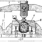 CLAMP FROM AIR…
One arm movement — and in an unusual vise clamped firmly from two shafts, the diameter of which can reach up to 120 mm. the Design of this hot clip is rather simple, based on it — four...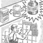 “BUSTILAT” DO
Glue "Bustilat" — a great helper in the household: they can bond a variety of materials. Another advantage is the simplicity of the composition, and therefore, the ability to cook it...
