 In the Arsenal of the Amateur radio voltmeter almost the most important measuring device. But the trouble is that to produce and it is not always possible. And not because the scheme is complicated. For many, the stumbling block is the arrow microammeter. However, at first it can be replaced by electron-optical indicator 6Е5С (6Е1П) or neon lamp. But first you need a high anodic voltage (up to 300V), and the second measures relicina capacity below 55 V.
These disadvantages do not have a simple voltmeter, which is an indicator… the light bulb 6.3 ВХ0,22 A. If the calibration is done thoroughly, the instrument error does not exceed 5%, and input impedance not less than 25 ohms/V, the Range of the measured voltages from 0.5 to 30 V AC and DC.
The voltmeter is powered from two battery 3336L or rectifier 9.
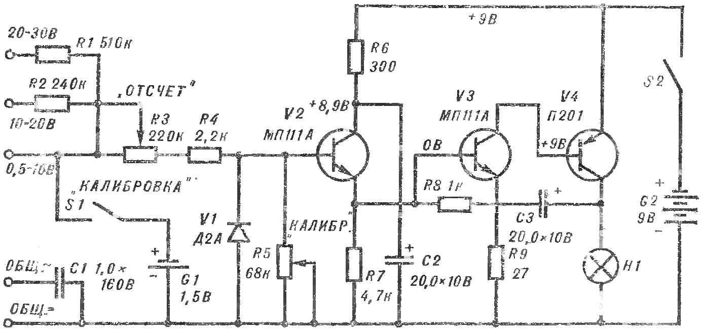
Schematic of the device (see Fig.) represents a threshold device with the switching voltage (based on V2) of 0.1 — 0.15 V. the Frequency of flashing of the lamp 59 — 65 times in min is almost independent of the voltage of the power supply.
The voltmeter operates as follows. When the switch S1 is open, the voltage at the input schemas is missing or is not enough to trigger the threshold device: the transistor V2 is closed. At the same time, the transistors VЗ and V4 are closed and the current consumed from the battery is almost zero.
When the measured voltage reaches the threshold value, the transistor V2 is opened, its emitter formed by the quantum potential. In turn, opens and transistors V3, V4. Lamp H1 lights up.
The capacitor C3 is charged to a voltage V4 of the collector and through the resistor R8, the current will arrive at the base of V3. The latter is closed and the lamp H1 extinguishes.
When the capacitor C3 is fully discharged, transistors V3, V4 will open again and the process repeated. The lamp H1 will flash with a certain frequency.
To extend the measuring range at the input of the device on the divider resistors R1—R5.
Rotate the resistor R3 “Countdown” before the lamp will flash. To the input of the voltmeter serves various voltages and changing the position of the resistor RZ, achieve that the lamp was flashing. According to the testimony of master graduate scale voltmeter a resistor R3 “Counting”. The engine variable resistor R5 “Calibration” should be approximately in the middle position.
Decoupling the chain R6, C2 V2 protects the transistor from the influence of flashing lights. Resistor R9 limits the current through the transistor V3, when the voltage at its base exceeds the limit, thereby protecting from the breakdown V4.

The transistors V2, VЗ — МП102, МП111А, МП37, KT315 with a small reverse current I to; V4 — П201, П213, ГТ403 with>30. Д2А diode can be replaced by D9, Д106, D2, D7 with any letter designation. Fixed resistors MLT-0.5, the variables SP-1A, the capacitors C1 — MBM, S 2, Sz — K50-3.
Calibrated voltmeter should be calibrated. To the input of the device connect the element FMC-0,25 a voltage of 1.5 V. the Knob of the variable resistor R3 is set to the level of “1.5” on a scale of “Countdown” and with the help of variable resistor I5 “Calibration” seek to stop playback.
The scale of the alternating voltage graduate as well as regular.
Before starting measurements, check the calibration of the device. Observing polarity, the input is the measured voltage. Rotating engine R3 until the lamp starts to ash, on a scale of “Countdown” read the measured voltage. If the light is not flashing constantly, it indicates that the voltage at the input of the device exceeds the selected limit of measurement.
A. VALENTINE’s


