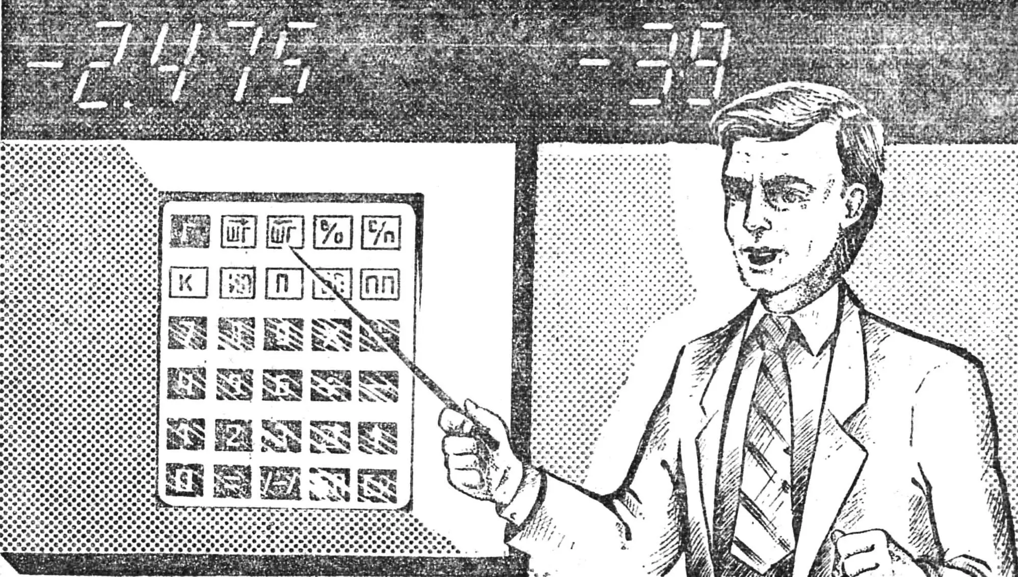
It is simply impossible to introduce students frontally to the rules of calculation and programming on a microcalculator if there is no enlarged demonstration analogue of it. Our magazine has already described a similar teaching aid intended for use in an ordinary school classroom (see “M-K” No. 4, 1986). Continuing this topic today, we acquaint readers with a lecture calculator designed for large auditoriums. It was built at the Rechnaya rural secondary school of the Kumensky district, Kirov region. It consists of a keyboard and a large-format indicator. The keyboard unit is a plywood box measuring 600X450 mm; on its face panel the keys measuring 50X50 mm are drawn, identical in color and legends to the keyboard of the PMK B3-34. In the lower left corner of each drawn key, the button of a microswitch is brought out; it is pressed when working with the lecture calculator. Under the keyboard is the PMK B3-34. Through the RSH2N-1-29 connector installed in its battery compartment, the lead wires are connected directly to the microprocessor board.
The light display measuring 2400X350 mm is made up of individual segments — glass tubes into whose ends lamps KM-24-35 or KM-60-55 are inserted by means of plugs (Fig. 1). The glass tubes can be made from chemical test tubes PH-16 by cutting off their bottoms. This is done mechanically or electrically. In the first case, a circular cut is made with a needle file at a distance of 90 mm from the neck, and then the unnecessary part is broken off. In the second variant, at the same distance the test tube is encircled with a turn of nichrome wire (from an electric hotplate spiral) and a current is passed that causes the wire to glow red. Then the current is switched off, the test tube is removed from the spiral, immersed in water to the heating level, and the bottom falls off.
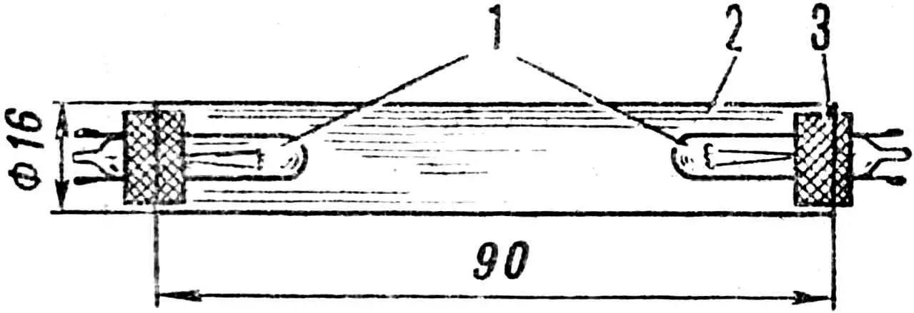
1 — incandescent lamps, 2 — glass tube, 3 — rubber plug.
To increase the brightness of the segment glow, a strip of foil of width π R (R is the tube radius) is fixed with Moment glue on the rear side of the glass tube.
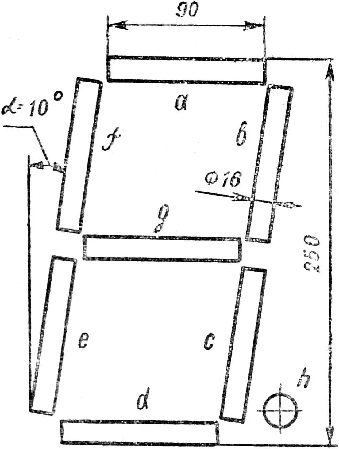
Each digit of the indicator consists of seven segments and one lamp — the decimal point (Fig. 2). The tubes are fastened to the plywood panel by means of wire loops located next to the plugs. The face of the display is covered with red transparent acrylic glass. It can be replaced with colorless transparent acrylic glass or ordinary window glass coated with cellulose lacquer in which red paste from a ballpoint pen has been dissolved.
At the base of the display, opposite each indicator, the digit printed-circuit boards are fastened with strips of oilcloth (Fig. 3).
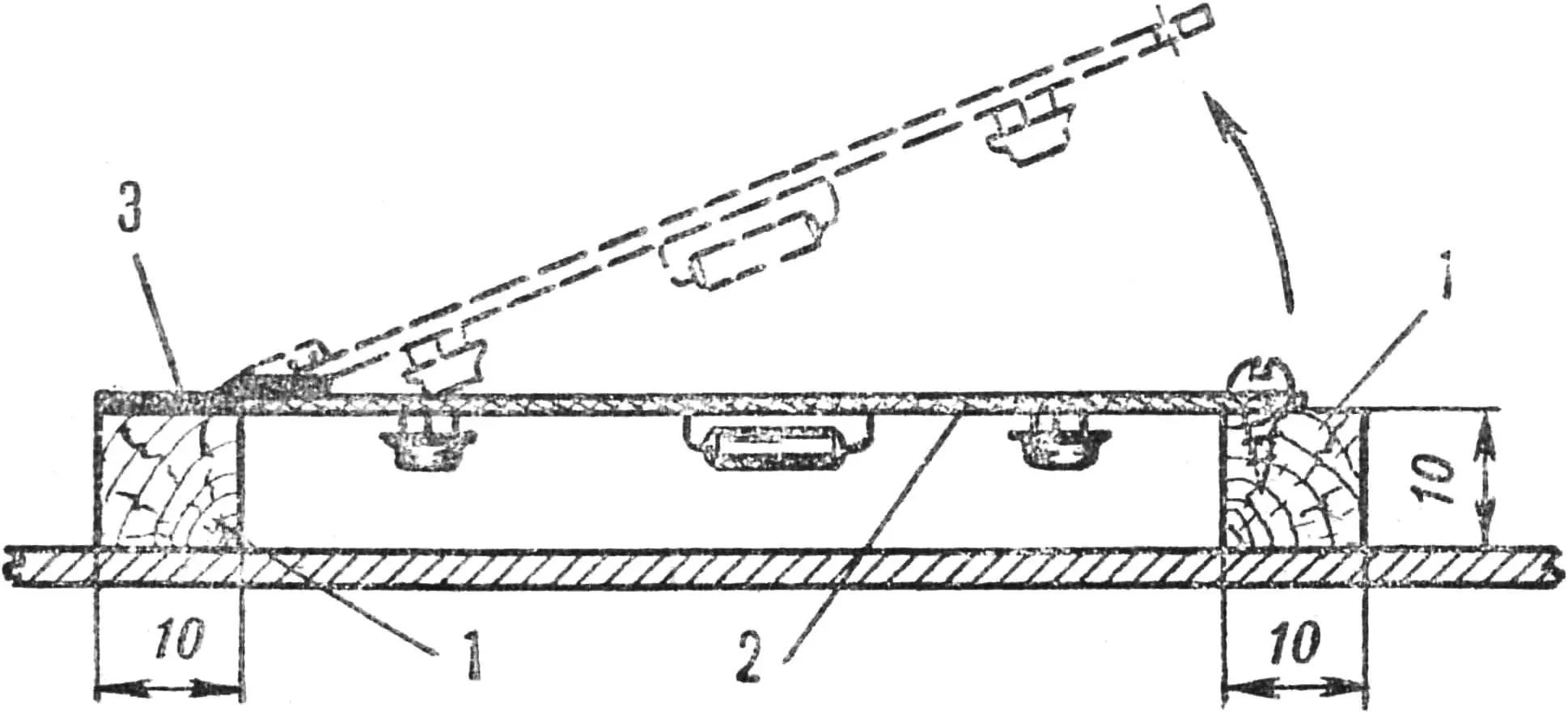
1 — wooden bar, 2 — board, 3 — oilcloth strip.
Now about the operation of the device. Control pulses from the anode terminals of the B3-34 indicator are fed through contacts 3—9 of connector X1 (Fig. 4) and resistors R2— R8 to pins 1 and 8 of ICs DD1—DD4. Resistors R2—R3 and Zener diodes VD3—VD9 form voltage dividers to stabilize the level of the incoming pulses. Pulses for forming the “point” arrive through contact 10 of X1 to pin 8 of DD4.3. The grid signal of the corresponding digit of the microcalculator indicator is fed through contact 2 of X1 to pins 2 and 9 of ICs DD1—DD4.
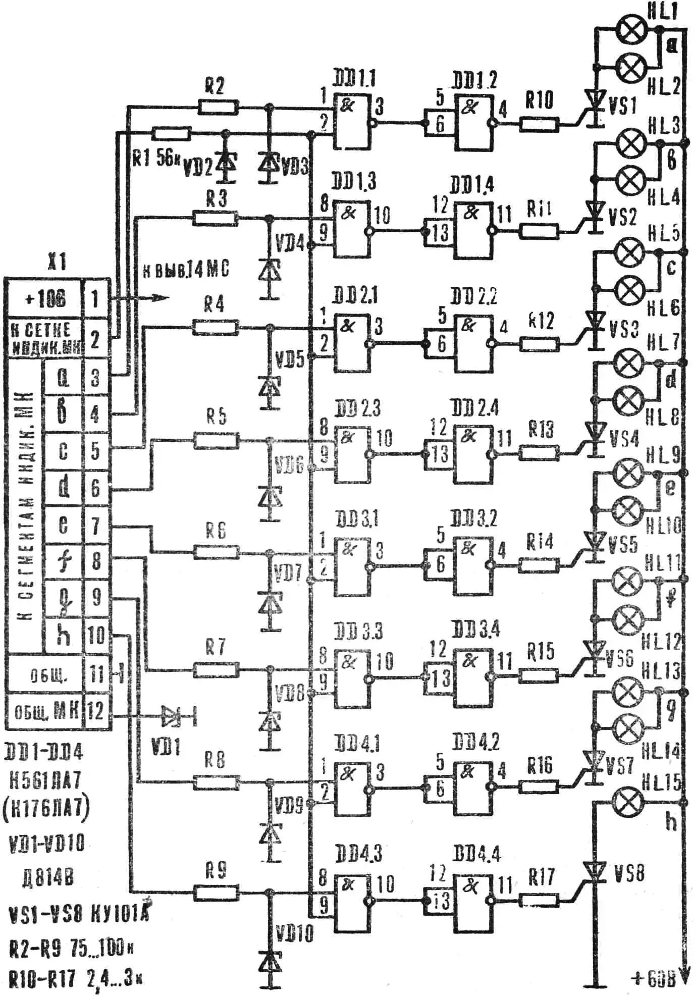
Let us consider the operating principle of the lecture calculator using segment “a” as an example. When logic-1 levels are present simultaneously at pins 1 and 2 of IC DD1, a logic 0 is established at the output (pin 3) and is applied to pins 5 and 6 of element DD1.2. A logic 1 (voltage 8.2 V) is formed at its output and, through resistor R10, is applied to the control electrode of thyristor VS1, which turns on. Lamps HL1 and HL2 light up, illuminating segment “a”.
If the pulses arrive at pins 1 and 2 of DD1 not simultaneously, this logic element (NAND) does not change its state. Consequently, a logic 0 remains at the output of DD1.2, thyristor VS1 is off, and segment “a” is not illuminated. The other segments of the light display operate in a similar way under the action of the commands formed in the microcalculator.
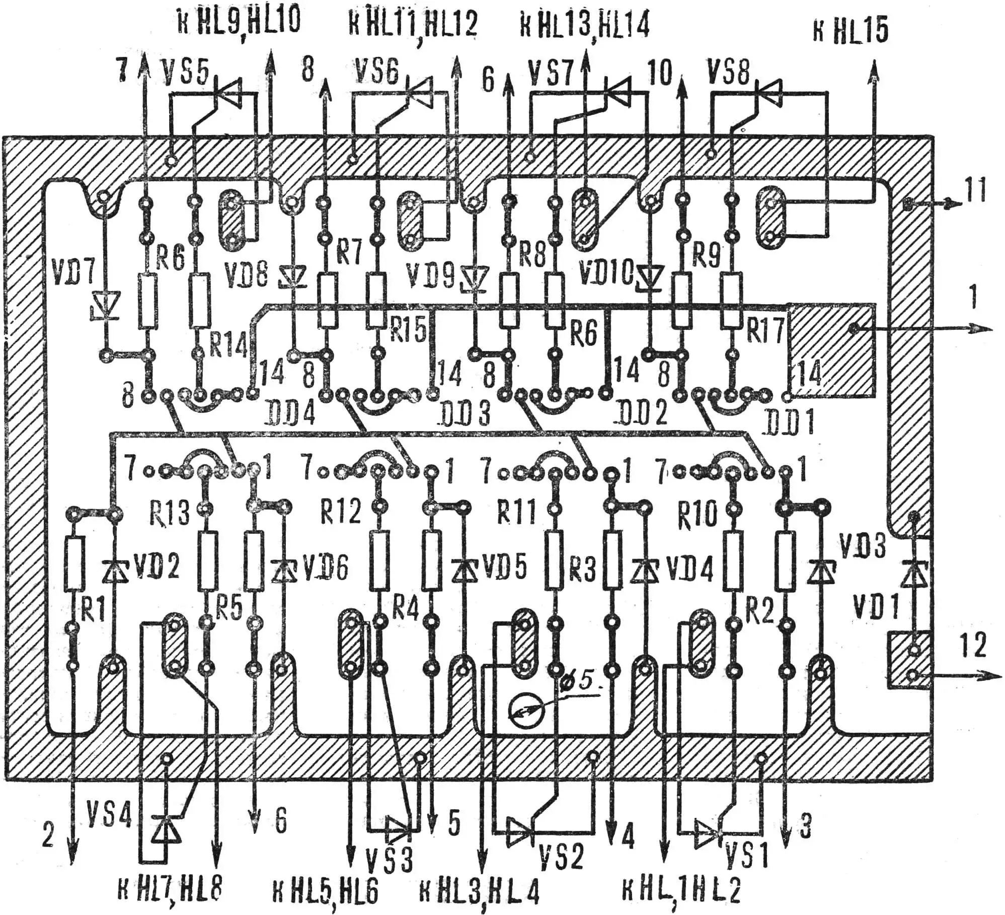
The printed-circuit board for controlling the indicator of one digit is shown in Figure 5.
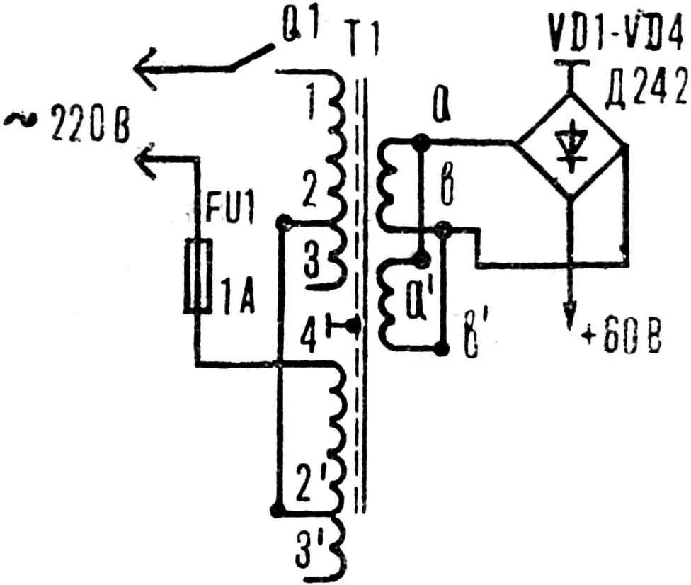
The characteristics of the power supply depend on the incandescent lamps used. For KM lamps we recommend using a transformer from UNT-47/59 television sets or a similar one of at least 180 W, for example TS-180-2. The transformer must be modernized: remove the secondary windings from each coil and wind two new ones of 85 turns each with PEL-1 1.0 wire. The rectifier circuit and the transformer winding connections are shown in Figure 6.
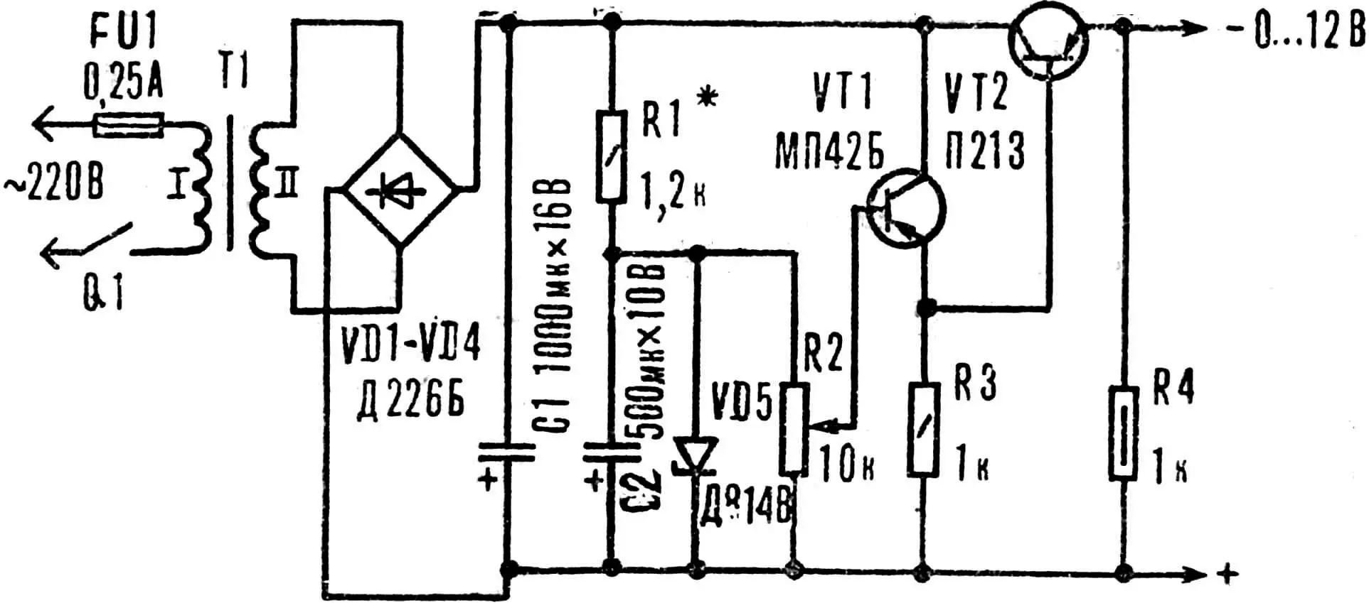
The rectifier circuit for powering the electronic part of the device is shown in Figure 7. With variable resistor R2 the output voltage is set in the range 9… 12 V, achieving clear turn-on of all thyristors.
With a sound component base and faultless assembly the lecture calculator starts working at once. Otherwise, using an oscilloscope, check that the pulse signal arrives at resistors R1—R9 (Fig. 4), and then that pulses are present at the IC inputs. If there is no signal at an IC input, check the corresponding resistor and Zener diode. Absence of pulse signals at pins 4 and 11 of the ICs (when they are present at the inputs and the wiring is correct) indicates that one of the devices has failed.
If the lamps of some segment continue to burn when there is no signal and the IC power supply is switched off, the thyristor of that segment must be replaced.
“M-K” 10’87, A. KARAVAYEV, V. SHILOV
Recommend to read
 MAGNET HAMMER
To fix the drawing paper on the drawing Board, a Board which is made of particle Board, is difficult. For anchoring one corner you have to use some drawing pins, as they bend. If you use... GARDENER-BUILDER
When the erection even garden shed great importance is the accuracy of the marking: for example, improperly laid Foundation can cause distortion and cracking of walls, roof and other...
