
 Why “multichronic”? Because this welding transformer (CT) has many important additional functions. If in traditional “svarochnik”, which has a magnetic core assembled from P – and sh-shaped plates, sometimes nowhere to squeeze at least one or two auxiliary coil, the proposed torus, a doughnut shaped design of the free space was enough. In the end, he is capable of AC/DC to cook “five”, and batteries to charge and metal melting, feeding safe voltage elektrovyzhigatel in circles “Skilful hands”, and perform a host of other things. Fit even to put the question differently: and what a winding and for what purpose wants to additionally have the user of this ST?!
Indeed, in the core “svarochnik”, which has the appearance of a “doughnut”, known in mathematics and technology Thor, a great future. Aware of this, but not having access to the special toroidal cores, industrial manufacturing, designed exclusively for transformers, homebrew forced to fit for their ST cylindrical ersatz from the old stators of electric motors with capacity of 1-1,5 kW. For this case of electric motors usually just break, laid in grooves winding unnecessary throw, the projections of the poles cut down. And in order for the resulting billet (rather resembling bagels, and too heavy crooked, bottomless pit) wound thickness of copper to achieve “super goals” is to make steel “five”!
I am convinced that it is not necessary to mangle the motors, even if they were in disrepair— a prudent owner will always be able to re-burnt winding and rewinding, and odysseyware bearings to replace. A rebuilt engine is capable of much more…
As for the proposed toroidal magnetic enough 5 — 6 kg of scrap transformer steel. Moreover, as the starting material here can be satisfied even with the same number of roofing iron (annealed).
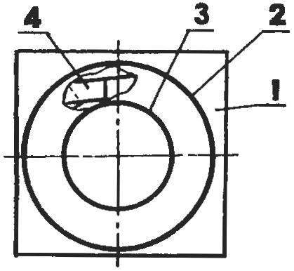
Fig. 1. The formation of a toroidal magnetic:
1 — base; 2 — outer cylinder-form (“Corolla” gear to run the starter GAZ-53); 3 — inner cylinder-form (60-mm section of steel pipe 100×6, slightly machined, wrapped two or three layers of paper); 4 — initial mass (of the plate with a width of 60-70 mm, cut from scrap from the W – and U-shaped plates of transformer steel, coated with quick-drying glue such as clerical, gum Arabic or oil paint and laid vperekryshku, with subsequent clogging of voids roofing waste)
The manufacturing technology of the magnetic circuit of such materials is quite simple (Fig. 1). The entire flat transformer steel scrap cut with scissors into strips about the same width.
Practice shows that often have to deal with rectangles with a width of 60-70 mm or slightly smaller counterparts, cut from P – and W-shaped plates. In the case are all “salestransactions” and roofing waste. After smearing both sides with some quick-drying glue such as stationery (liquid glass), gum Arabic, or even cheap oil paint them tightly laid with a slight overlap into the formwork (as when casting a hollow concrete columns) from scrap materials.
In the author’s technology of the inner cylinder of the casing (Fig.1) is 60 mm section of steel pipe 100×6 mm. Inside must be machined slightly on the cone and wrap (so that it is subsequently easier to remove from the “molded” magnetic core) two or three layers of paper strips. And as in external use removable “halo” gear (inner diameter 250 mm) — from the starting system starter the car GAS-53.
Of course, you can apply for formwork and other suitable workpiece capable of withstanding the mechanical stresses that occur when “casting” a toroidal magnetic core. And they — a lot, especially when all slots have a hammer to hammer small plate (preferably to fit the width of the set).
Once the glue dries, the toroidal core can be considered almost finished. However, it still needs to be done unilaterally rounded semiring-“probablity” of insulating material. At least out of plywood —for the best styling future of the windings and eliminating short circuits on the sharp edges of the magnetic core. This will contribute to pre-wrap the Torah in two or three layers of surgical tape, fiberglass, or fabric strips, impregnated with linseed oil.
Now about the windings “svarochnik”. Science claims, and the practice clearly shows that the transformer operates in a favorable mode for it, if in its windings through a 1 mm2 cross section copper wire passes current equal to 5 A. Under extreme conditions, this figure could rise to 13 A, but the wires become very hot and burn out.
For welding 3-mm electrode required current of at least 80 A. Hence, the cross-section area of copper cable or power (welding) tyres must conform to it. Taken with a substantial margin, it is for good homemade welding transformer is usually in the range of 25 to 35 mm2.
Starting from the already mentioned “minimum welding” 80 and in view of the widely practiced, the ratio of turns of the network winding, and a power of about 5:1, we find: current network of the winding should be not less than 16 A. it follows that for mounting the network coil need to take copper wire 3.2 mm2. However, the best, perhaps the option — ПЭВ2 with a diameter of 2-2,5 mm.
Considered to be (and this is confirmed in practice) that the “molded” magnetic core having the cross-sectional area in the transformer steel, is 40 cm2 each coil winding will correspond to the voltage of 1 V. taking into account the possible instability of the supply network, the winding should be done with the stock.
The landmark 250 turns. In this case, after 190 it is desirable to provide (without cutting wires!) every ten turns the taps. Of course, the switch should be reliable enough to ensure good electrical contact in order to avoid large energy losses and a strong heating during operation of ST.
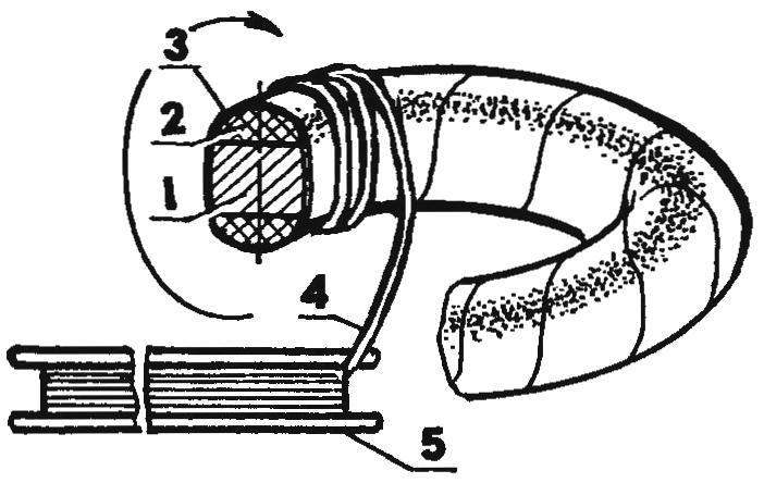
Fig. 2. Laying of turns of the winding network “svarochnik” (magdalaine the insulating gasket is not shown):
1 — toroidal magnetic core; 2 — sided rounded semicircle-“probably” of insulating material (2); 3 — fixing the insulating spacer (2-3 layers of surgical tape, fiberglass, or fabric strips, impregnated with linseed oil); 4—wire network winding (ПЭВ2, Ø2—2,5); 5 — wooden Shuttle
In fact, the winding network winding operation is quite difficult. It has to perform with a long wooden hook (Fig. 2). Done carefully, avoiding perekrashivaniya turns, nodules and damage to the insulating lacquer on the wire. Otherwise, we can expect the appearance of interturn short circuits and overheating of the transformer.
If you place the core on two supports with a soft surface (lining), eliminating damage to the wire insulation during winding of the CT, then the whole job will take about two hours. To finish it preferably “in one pass”, so that the winding is not attenuated and was most dense, with insulating spacers between the layers.
After the network is wound, it is good to check it at idle. Even if for long time the magnetic circuit with a coil will be just barely warm, then everything is fine. Considerable heat is an indication that either of the coils a little, or contains a winding short circuit (and sometimes breakdown of the windings on the case!).
Two or three-layer insulated winding network needs to be stacked with secondary welding, or power. And this is from 40 to 80 turns of copper bar or stranded cable. The latter is preferable for the following reasons: it can be directly done welding the sleeve; substantially easier winding; increasing the life of the welding winding with simultaneous simplification of the operating conditions, which is especially important when experimenting with this ARTICLE. It simplifies the connection of the rectifier and the possibility of effective regulation of the welding current and voltage by performing elementary operations of winding or otmachivanija of turns of the cable.
For a homemade not too powerful welding machines are desirable on the following schedule: minute — welding, two in technological interruption for cooling of ST. Good result gives application of small fans. Probably even more can be achieved when used for cooling “svarochnik” protozoa radiant heating radiators and mineral oils, can improve the insulation of the windings ST.
Solid welding transformer must have a steep characteristic. This can be achieved by dividing the coil into two equal parts. On one side of the core are wound with half network and half of the power winding, and on the other — the rest (and to subsequently not be confused — in the same sequence).
It is useful, apparently, to remind you that the transformer — the device is reversible: if for any winding connected to an alternating voltage, for which it is designed, on the other there are those U~, for which they are intended. By the way, similar to what a lot of hams in the determination of the windings in an unknown transformer.
Given the above, not necessarily the network (primary) coil TC wound first, and then on top of it and welding (secondary). The sequence of winding as their serial numbers, only the condition for a more rapid and habitual orientation in the circuit diagram “svarochnik”. So if, say, it is necessary to wind one of the windings sufficiently rigid bus, with the laying of which will have to resort to the mallet, then, of course, this “copper” is more convenient to place first at the core, in order not to damage more compliant and vulnerable leads of the other windings.
And again. If any coil has enough wire for the other windings it is very small, then first get to the part where your options are limited. Because with the apparent lack of cable or bus to power (welding) winding, but with the availability of powerful diode— semiconductor valves is profitable to abandon the welding on AC in favor of DC (Fig. 4). In this case, the voltage of ST and therefore the number of turns in the welding winding is sufficient to have a minimum. If the bus — with damaged insulation, it is recommended that it first be annealed by cooling in water (copper is soft), sealed with shellac and fiberglass and only then start winding on the magnetic core.
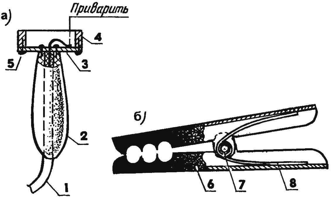
Fig. 3. The options of devices to contact “earth” — magnetic (a) and clamp type “crocodile” (b):
1 — welding cable; 2 — handle; 3 — steel plate; 4 — ring magnet-“stuck”; 5 — screw (quantity and location — on-site installation); 6 — half a homemade “toothed jaws” pegs (cut from a steel pipe of a suitable size, 2); 7 — steel axle, rastrepina on two sides; 8 — spring
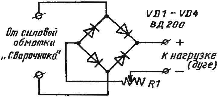
Fig. 4. Schematic welding rectifier with a current regulator for a homemade multimarochnaya transformer (R1 — a spiral of nichrome wire with a diameter of 3-5 mm with movable neogeobrteam contact)
Often, the homebrew having trouble connecting the power cable to the welding product: the contact is bad, “privatise” to nothing. To help in such situations two devices (Fig.4): magnetic and clamp type “crocodile”. Both diys are very simple to manufacture, quickly and conveniently attached. In the absence of proper contact enough to RUB on the item.
It is a good idea to equip a network winding ST standard machine up, designed by no less than 30 A, it is convenient to disconnect the transformer in the pauses between welding. This will significantly save electricity, will create favorable conditions for the timely cooling of the apparatus, make the operation safer. Well, the presence of a powerful rectifier (Fig.H) allows, as already mentioned, to use the unit when charging the batteries or organization multioperator power, for example, low-voltage soldering irons and elektrovyzhigatel in school circles “Skilful hands”. Moreover, this unit is truly indispensable, for example, in the production of electroplating work at home or start your car in cold conditions.
Very interesting and promising is to equip ST extra winding, only containing one full revolution of annealed copper bus 5×50 mm or thick stranded copper cable with a diameter of about 20 mm (with the trailing edges of the segments of thick-walled copper pipe). As shown, with the help of such a winding it is possible to hot free forging, tempering and blueing, brazing and welding; bending the metal strip, pipe, thick steel rod, “logs”, fragile wire; casting of tin, zinc, lead; turn “stuck” bolts, studs and nuts; spot welding, shrink-fit and a number of other operations.
How to make a smooth adjustment of the current? Yes, at least the above-mentioned way of adjusting the power (cable) winding. When rewinding part it from the magnetic circuit decreases the voltage while increasing the current from a CT, but worse, in particular, conditions for the ignition of the arc. Conversely, Domotica cable leads to the growth of the transformed voltage while reducing current output to the load. The electric arc thus better lit.
Or another option, when the welding cable connected to the product directly, but through a few turns of wire with high resistance (e.g., nichrome). Resistant how many turns — so many stages of adjustment of welding current. Arc is ignited in all cases almost the same.
Adjustment of the current ST can be realized with a combination of gate valves, made of transformer steel and non-ferrous metal. In this case, the magnetic core is performed a transverse cut.
Plumbers, drivers, repairmen and fans to make all their own hands, this “svarochnik” with such versatile features for you.
R. KRAVTSOV, city of Yeysk, Krasnodar Krai
Recommend to read
 STATIONERY – ROOFING
In stores are not always available in the sale of special roofing nails. Therefore, in order not to waste time looking for, use the usual stationery buttons, nails on nails. S.... LOFT WITH COMFORT
The living area of this summer house is almost twice the space it occupies in the garden. The secret is simple: the previously empty attic was turned by skillful hands into another...
