MULTIRANGE TIME RELAY

MULTIRANGE TIME RELAYTime relay, the readers, used in the automation devices in the workplace and at home. The device is simple in design, has small dimensions, is reliable in operation, but its main feature — a large range of exposures.
Construction electronic time relay on the principle of charge-discharge of the capacitor on the exposure of more than 10 min is a challenge. High resistance discharge circuit is exposed to the action of climatic factors (especially humidity), and if not to accept special measures, the stability is low.
 
Time relay, which uses a reference generator with frequency divider and a decoder is less susceptible to external influences. Therefore, such devices with significantly (higher stability, it is possible to build exposure in the tens or hundreds of hours. However to make these devices difficult.
 
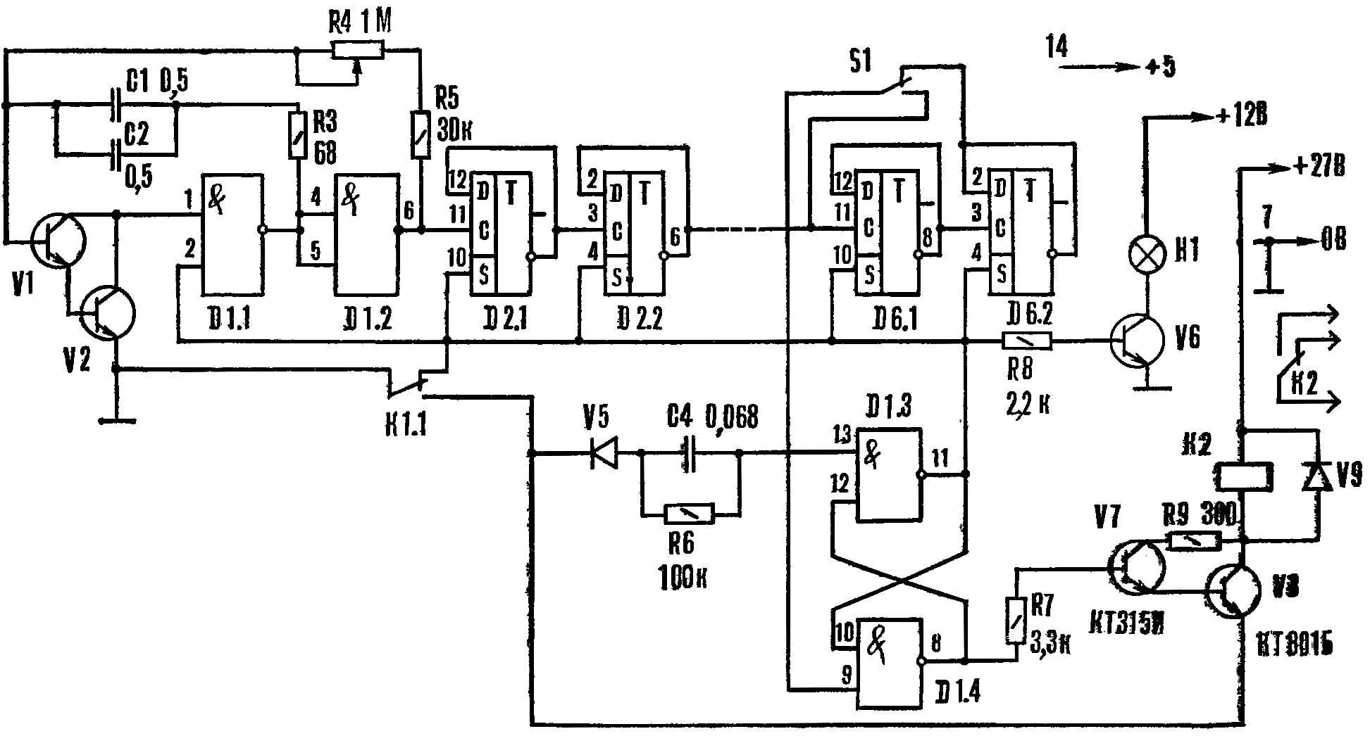
Design, which is described in this article combines the advantages of the mentioned devices and at the same time available for repetition in Amateur conditions. Schematic diagram of the time relay is shown in figure 1. Transistors V1 and V2 with elements of D1.1 and D1.2, capacitors C1 and C2, resistors R3, R4 and R5 form a generator; the frequency set by the variable resistor R4. The generator output is connected to the frequency divider, assembled on integrated circuits D2 — D6. With its output signals being received by one input of RS-trigger assembled on the elements of D1.3, and D1.4. The other trigger input connected to the trigger circuit.
Fig. 1. Schematic diagram of the time relay
Fig. 1. Schematic diagram of the time relay:
K1 — RES-10 (RS4 passport.525.301), K2 — RMU (passport RS4.523.303), H1 — CMH-10-55.
 
One is RS-trigger connected through the transistor V6 to the indicator light H1 and the second through the transistor V7 and V8 to the relay K2.
 
Launching AC voltage of 220 V is supplied through resistors R1 and R2, the diodes V3 and V4 and the capacitor C3 to the relay K1. In the initial state, when the triggering voltage is not present, the contact K1.1 connects the generator and it does not work. Triggers frequency divider are also located in the source position: signal lamp H1 is not lit. Relay K2 de-energized, although at the base of the transistor V7 is a high level voltage (emitter V8 is disconnected from the “common” wire).
 
When the input signal is supplied, relay K1 is triggered and its contact K1.1 switches. At this point, the RS-flip-flop changes its state on the opposite — on the output 11 of the element D1.3 becomes a high level voltage, and the output 8 D1.4 — low. Signal lamp H1 lights up but relay K2 remains energized, since on the basis of the V7 appeared a low voltage level. The generator produces pulses which are fed to the frequency divider. With the advent of the low level at the output of the last element of the frequency divider RS-flip-flop switches to the original condition at the output 11 of the element D1.3 becomes low and at pin 8 D1.4 — high. The generator slows down, the lamp H1 extinguishes and the relay K2 is activated (the contacts K1.1 remain closed until the disappearance of the triggering voltage).
 
The device provides a delay in the receipt of the Executive relative to the triggering voltage for the time controlled shutter speed. It is defined by the oscillator frequency with a resistor R4, and a large-scale switch S1. It is clear that the higher it is, the shorter the exposure time, and the larger the division ratio of the frequency divider, the longer. The oscillator frequency can be rebuilt seamlessly in the wide limits, and the division ratio — jump 4 times. The scale of the relay corresponds to 6 min, and the circuit S1 becomes equal to 1,5 min.
 
To build a time relay delayed by 24 min., enough to add another chip К155ТМ2. Thus, adding a single chip increases the exposure time 4 times. While the increase in the capacitance of the capacitor C1, C2 or the resistance of resistor R4 should not be, because it deteriorates the stability of the first pulse generator.
 
Correctly assembled device begins to work immediately. Commissioning is reduced to a graduated scale which is practically uniform when using a linear resistor (R4). The calibration is easy to perform, if after the first element of a frequency divider to measure the pulse duration and multiplied by the division ratio of the remaining part of the divisor.
 
When measuring the terminal 9 of the element D1.4 disconnect and start the generator. This method of calibration significantly reduces the time to conduct this operation because you do not have to wait until the end of the period of maximum exposure.
After calibration, the circuit of the relay is reduced. To the output 11 of the element D1.3 connect the electronic timer and additionally check the correctness of the grading scale.
 
Time relay, collected on the chip series K155, is sensitive to interference, penetrating power circuits. So they must block capacitors.
 
Fig. 2. Schematic diagram of the power supply.
 
Power supply diagram is shown in figure 2, is designed for the kit, consisting of six relays. This kit was shown on the 29-th all-Union radioactive. He was awarded a bronze medal VDNH.
 
T1 is made on the core from a TV transformer TVK-110. The primary winding (pins 1-2) wound wire of PEV-2 0,12 and contains 1760 turns, secondary winding (pins 3-4) has 90 turns of wire PEV-2 of 0.71, the third (terminals 5-6) is 200 turns of wire PEV-2 0,21.
 
O. LAZARENKO, balanove, Saratov region.

Recommend to read

  • REFRIGERATOR… DOORREFRIGERATOR… DOOR
    In winter, many Housewives are storing on the balcony. But some products cannot be "deep freeze". In this case, it is very convenient to use the balcony doors. If they are dual (1) — in...
  • SAW-SHARPENERSAW-SHARPENER
    Do not rush to throw the old cloth nozhovki on metal — he still can find application. Fragments, for example, I use for sharpening knives. The holes are pruned to 6 — 7 cm, scroogle them...