OBJECTIVE EXAMINER

OBJECTIVE EXAMINERIn the sixth issue of our magazine in 1974 we told about the device “Pulse” for the control of knowledge of students. Practice operating the machine created by the participants NTTM Donetsk Polytechnic Institute, as well as the feedback from readers has convinced authors of the need to improve the design.
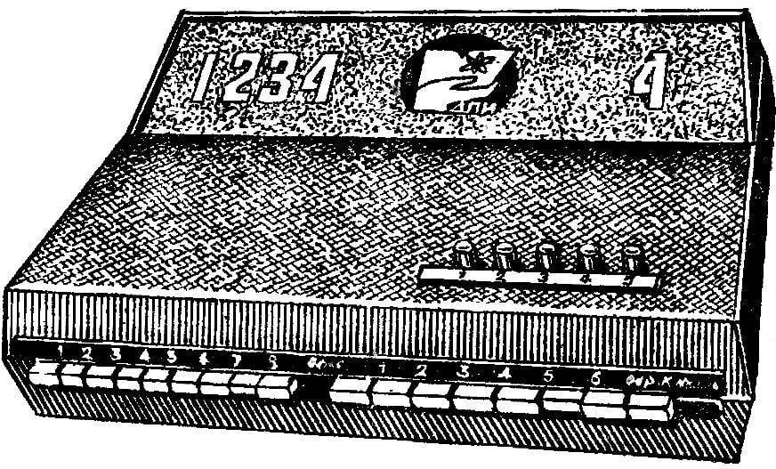
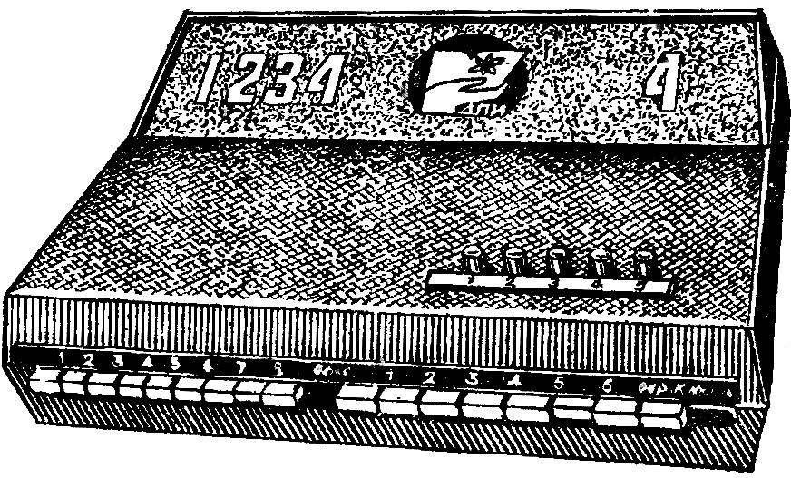
And that’s as a result of the creative efforts of teachers and students “Park” machines programmed training at the Institute now updated: the former, now obsolete, the device replaced the more perfect his fellow “Pulse-3”. The changes were primarily a code memory of the machine, system of checking students ‘ knowledge and the lock-up device. More attractive he became and the appearance of the device. About the new development tell the engineers L. Zinoviev, R. Kovalenko and M. Dinning.
 
The device consists of five blocks: encoding, in the order of working out of the question and memory correct answers, adder, lock, and reset power.
 
A coding unit consists of two series-connected switch S7, S8 (see scheme). To the inputs of S7 connected to button S2—S6 record responses. Outputs S8 are connected with the relay memory correct answers K5 — K9. The combination of the connected contacts of the switches S7, S8 determines 48 variants of the code. (In two-digit number indicating the version of the ticket, the first and second figure refer respectively to the switches S7 and S8.)
Device order are working on the issue consists of relay K10 — K14, capacitors C2 — C6 and diodes, V32 — V36. The contact plate of the relay is included so that the disconnection of the previous contact groups occurred when switching later.
 
In the initial position (of the lit lamp D1) the chain of relay K5 is connected to the “minus” of power supply. Enter the answer by pressing buttons S2 — S6. Relay K1, and through its contact K1.2 charging the capacitor C2. At the same time, if entered correct answer relay K5 through contact circuit S7, S8 and K10.1—K13.1.
 
When you release the button enter answers, the relay K1 returns to its original position and the capacitor C2 is discharged through the break contact K1.1 on the left-hand winding of relay K10. It works, and contacts K10.1, K10.2 switch to the lower position on the scheme in which they will remain after the discharge of the capacitor C2 (these are the design features of the RPS-20). Prepared circuit discharge of the capacitor C3 included indicator H2 (H1 extinguished). At the same time through the contact K10.1 to “minus” of the power source is connected DEWA coil K6.
 
When you enter the answer to the second question is again triggered, the relay K1, the contact K1.2 closes the circuit to charge the capacitor C3, and contact K1.1 opens the circuit discharge of capacitors C2, C4, C6. Simultaneously entering a correct answer relay K6 through contacts K10.1 (lower position) and K11.1, K12.1, K13.1 (upper position). Its contact K6.2 it is preparing to turn the lamp H2 (via K14.1).
 
Concept of the controller
Schematic diagram of the controlling device:
K1 — relay RES-9 (passport RS4.524.211), K2—K4 relay RES-10 (RS4 passport.524.302), K5—K14 relay RPS-20 (passport RS4.521.754П2); H1— H9 bulb LN 26; S2—S6 buttons ГР3.604.003, S7, S8 — push-button switches П2К, S9 — button MK1-1; R1—R9 resistors MLT-1,0; C1—C6 capacitors C50-3; T1 transformer 220/24 V, 20 watts.

 
Once the answers are introduced to all five questions, relay K14 evaluation, which by its contact K14.Includes 1 lamp, H1 — H5 of the order are working on the issue, h6 — H9 estimates and the output of the voltage divider.
 
The adder performed on the transistors V24 and V25, V27 and V28, V30 and V31. The closure of the contacts K5.1 — K9.1 memory relay correct answers leads to a change in the voltage drop across the resistor R5, which is applied to the Zener diode V23, V26, V29 with different values for voltage stabilization.
If you have entered all the correct answers, the voltage drop will be such that all of the Zener diodes will work. The transistors V24, V25, V27, V28, V30, V31 open, and relay K2 — K4 Triggered, including the lamp H9, illuminating a score of “5”.
 
4 if you entered a correct answer, the voltage drop across R5 will provide the trigger only relays K3 and K4, which will include the H8 bulb illumination estimation “4”.
 
Accordingly, when the three correct responses, relay K4 closes the power circuit of the lamp H7 rating of “3”.
 
When correct answers less than three contacts of K2.1 — K4.1 remain in their original position, which signals the lamp h6, illuminating a rating of “2”.
 
The device used to lock precluding the simultaneous entry of responses a few buttons. It is obtained by successive switching of the contact plates S2 — S6. As a result, when any button is pressed, all subsequent circuit is opened, and pressing the previous switch issue.
 
The unit lead to its original state by pressing the button briefly S9. The voltage of a particular polarity supplied to the right relay coil K5 — K14, transferring their contacts to the original position.

Recommend to read

  • SCREW-OUT RIVETSCREW-OUT RIVET
    The screw securing the knob or handle on vodozabornoy valve (valve, tap), made of bronze or brass. If it's lost or fallen into disrepair — not to screw in its place steel, even briefly,...
  • CATERPILLAR AROUND THE SKI: THE EXPERIMENT CONTINUESCATERPILLAR AROUND THE SKI: THE EXPERIMENT CONTINUES
    With the magazine "modelist-Konstruktor" I've known since high school, often picked up from the magazine interesting ideas, implemented them. Over time, accumulated their own experience,...