In a previous article under the heading “electronics for beginners” (see “M-K” № 8, 1979) we understand how magnetic field is formed it Turned out that, in particular, generates supplied to the coil (solenoid) electric current. The same field with a certain force acts on it carried to the magnet. But the magnet with the same force acts on the wire, which carries current. On the phenomenon of the interaction of electric current and magnet based electric motors (electric motors).
Any electric motor consists of two main parts. Creates a stationary magnetic field is the stator, which is a permanent magnet or a field winding, the rotating part — the rotor.
How does the motor? Between the poles of a permanent magnet (stator) is a rotor — a coil of wire: it flows an electric current. Such a coil with a current creates a magnetic field.
Interacting with a permanent magnet (stator), the North pole of the coil (rotor) is attracted to the South pole of the magnet and South to North. If you now change the direction of the current in the coil, the location of the poles of the rotor is also reversed. Near the North pole of the stator will be a North pole loop, near South — South. There’s a repulsive force, and the round will turn a half turn. A new change in the current direction will cause the turn another half turn, etc.
Changes the direction of the current in the rotor winding is a special device — the collector. The simplest collector is a metal ring divided into two halves. Each half ring is connected to one end of the rotor winding. The half-rings are pressed against the brush of a metal plate connected to a current source. The brushes pass from one half ring to the other, and the direction of the current in the rotor winding changes. So it rotates continuously. This is how the DC motor.
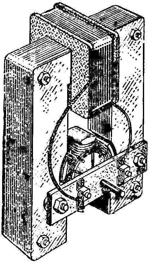
And now we offer ourselves to manufacture electric motor for moving models (Fig. 1). Start with the stator. In figure 2, cut out 18 plates of annealed steel (e.g., tin) with a thickness of 0.5—1 mm. In plates drill 4 holes Ø 2.5 mm: they will need for tightening bolts. Next bond all the plates together, treat yourself with a file the ends of the stator, focusing on its inner surface. Its diameter should be equal to 41 mm.

 In a previous article under the heading “electronics for beginners” (see “M-K” № 8, 1979) we understand how magnetic field is formed it Turned out that, in particular, generates supplied to the coil (solenoid) electric current. The same field with a certain force acts on it carried to the magnet. But the magnet with the same force acts on the wire, which carries current. On the phenomenon of the interaction of electric current and magnet based electric motors (electric motors).