
 Without pretending to any special built in circuitry to use a more graceful version of an intercom that can be used as an intercom system in the private house or in the country. The design is simple and available for self-production, even a novice radio enthusiast. In standby mode the device does not consume battery power, but is always ready to work: just touch the button and — please say! Working on the second set you will certainly hear.
As the hardware components selected germanium transistors MP. Affordable, cheap and reliable, they have parameters sufficient for use in this negotiating unit. Moreover, ‘it is useful to remind you to “bring to life” a silicon transistor requires about 0.6 V For push-pull output stage, this number should be doubled. At the same germanium semiconductor triodes consumption is halved, which can not affect the maximum achievable span of the output signal.
Among the advantages of the proposed development — the de-energization of the corresponding amplifier in the reception mode, the SB1 button simultaneously connect it directly to SA1 loudspeaker lines. The signal coming from another device (the second set), virtually all of which is supplied to the speaker, the impedance of the voice coil which, as a minimum, three times less than the input resistance of the amplifier through resistor R3. Such circuit design allows, in contrast to analogs with a complex and expensive multi-way switches that do only one (and not scarce) button type KM2-1 of domestic production.
Clicking on SB1 (working in transmission mode) the amplifier is connected to the battery power supply, and speaker, is removable from the communication line, is used now as a kind of microphone. The output signal through the closed contacts 1′ and 2′ out in the line. The purpose of the R3 — stabilization of the input stage, assembled on VT1, when the temperature changes, the voltage change of the transistor. Parameters of the chain R6С5 are selected to improve the transmission quality of the speech signal such that the second cascade on the VT2 provided more gain at the high audio frequencies than at the lower.
The sensitivity of the amplifier VT1 — VT5 is pretty big. To exclude the possibility of self-excitation of such a device due to parasitic relations of power circuits and at the same time to increase its immunity, the first two cascades are separated from the rest of the filter C6R7C7.
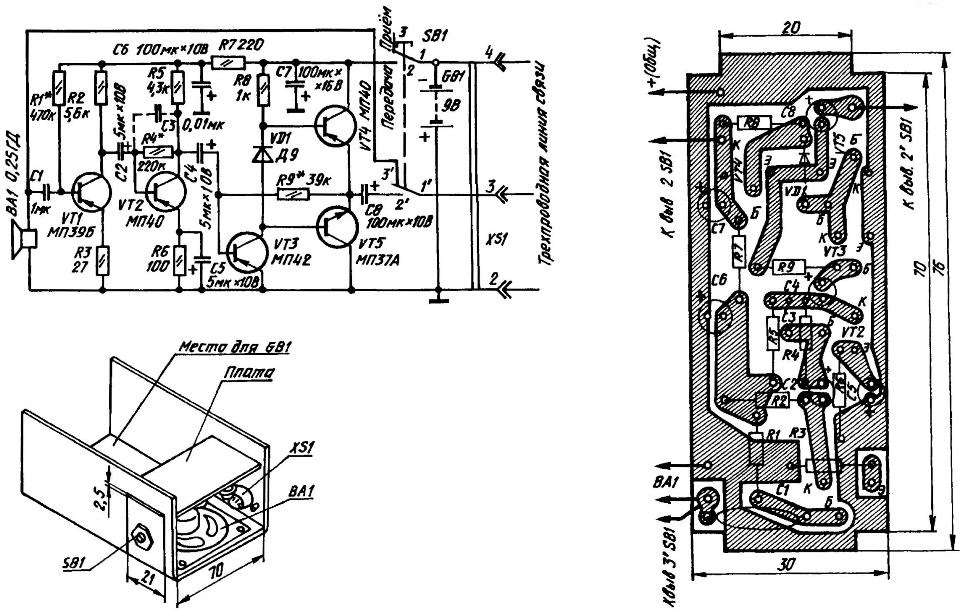
Circuit diagram, PCB layout and arrangement of major components of the apparatus for a homemade intercom
In the schematic and on the PCB the setting of C3 is to limit the bandwidth of the amplifier and prevent self-excitation on high frequencies. However, the Assembly of multiple copies of the showed that the device works well and without the above-mentioned capacitor. However, if suddenly there is excitement in the form of a thin squeak or users will find the tone too high, then the situation can easily be corrected by returning C3 to intended for him.
The output stage is assembled on the transistors VT4 and VT5, is a push-pull emitter-follower. Voltage it appeared, but is able to give a significant load current, which is especially valuable when working on a speaker with a small resistance of the voice coil.
Between bases of transistors VT4 and VT5 included diode VD1. Its purpose is to reduce harmonic distortion in the output push-pull cascade.
Now, the radio components needed to build this device. Resistors of any suitable type, with a capacity of 0.125 or 0.25 watts. Capacitors C2, C4 — C8 electrolytic K50-6, K50-16 or K50-35. But with C1 the situation is somewhat more complicated. Because it is exposed to voltages of different polarity, so for reliability, this capacitor should be electroless. In the author’s options, for example, successfully used K73-17, designed for work in AC circuits, pulsed and DC. Can also be used in the monolithic ceramic capacitor of the type KM with a capacity of 0.68—1 UF.
The device isn’t critical to the selection of semiconductor devices for their installation. In particular, suitable for the VD1 diode of the series D9, D18, D20 or Д311. And with any alphabetic index. As p-n-p transistors VT2 — VT4 suitable type МП14, МП16, МП39-МП42, МП25. VT5 is acceptable for any of the semiconductor triode n-p-n series МП36—MP38, МП10 (alphabetic index at the end of the name in this case does not matter).
But the VT1 transistor it is desirable to use a low noise. Otherwise fluctuation of the background from the first amplifier stage, having appeared as a characteristic hiss, will be comparable to a weak input signal, and after appropriate amplification on VT2— VT5 will be reproduced by the speaker in the second set of equipment.
But there are plenty to choose from. In addition to a low-noise transistor МП39Б, specified in the scheme, will fit МП27 (П27) or МП28 (П28).
The PCB for both models is equal. Foil “common wire”, thus forming a closed circuit, serves as a kind of screen, further protecting the amplifier from interference. The installation is quite dense, so first install the resistors and diode, then there are capacitors, and the latter transistors. To prevent accidental contacts on the metal casing of the electrolytic capacitors wear of PVC pipe of suitable diameter. And in order to avoid short circuits through the possible damage of the solder — clean the knife with the narrowest gaps between tracks, especially near lunch.
Establishing device is reduced to the selection of resistors R1, R4, R9, ensuring the proper operating mode of the amplifier. In particular, make the voltage at the collectors of VT1, VT2 and the emitter VT4, VT5 was half of Usup. This operation is desirable precisely to do for the output stage, and in the preliminary permissible 1,5-voltage deviations in the smaller and in a big way. Moreover, if the voltage is not enough, then the resistor should be increased, and in the opposite case — on the contrary, to reduce.
The above resistors on the debugging schemes of the solder from the foil. A transistor can fail, if the collector and the emitter is powered when disconnected database.
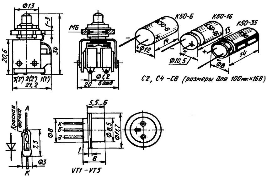
The Pinout of the switch button and the polar elements used in improvised negotiating unit transistors
For the final test of the amplifier connect to terminals 2 and 3 of the connector on the speaker. Dynamic head position (to avoid self-excitation of the entire device due to acoustic feedback) to 3-4 metres from the camera. Press a button and speaking into the microphone, make sure the admissibility of the transmission quality. At the same time determine the optimal distance between mouth and microphone. Remember: at a small distance the sound is too low and somewhat distorted, and with great quiet.
The power of each of the devices is carried out from a galvanic battery “Crown”. But it is possible to use 7 disk batteries with a capacity of at least 0.1 Ah or power supply (preferably stabilized) type BP-02Б2, which are equipped with some portable domestic recorders. When using batteries, can not do without a charger, which may be improvised (e.g., for development, published in the journal “modelist-Konstruktor” No. 9 in 1998).
In conclusion, a few tips are addressed to beginners in the field of electrical and radio engineering. The sharp increase in current consumption and a strong heating VT4, VT5 can also be a malfunction or an incorrect inclusion of VT3, VT4 (VT5), a small value of resistance R9, a breach or violation of polarity korotkopushistye conclusions when installing a C4 or C8. It happens that the blame for the malfunction or incorrect insertion of a semiconductor diode VD1 and the error in the polarity of the power supply.
If it starts to get dark or lit protective paint on the resistor R7 is then punched, closed during installation or improperly switched capacitor SB. It is useful also to assure the correct polarity of the power supply circuit.
Another common beginners ‘ mistake when, instead of the resistor to 470 ohms mistakenly soldered 470 Ohm, that is the value, which is 1000 times less than required. Be attentive to the legend on the radio!
Further inspection of the mounted device should be carried out from the outlet to the inlet. Tweezers by grounding the “common wire” in turn bases of transistors VT3, VT2, VT1 (short-term to do it in this scheme are not dangerous), reveal the “whimsical” (if any) cascade — the lack of crash dynamics and the increase in the voltage at the collector. Found fault eliminate.
As a rule, an important problem for beginners in ham radio is making a body for their homemade products. Solve it in different ways. Good results are obtained, for example, with a U-shaped plastic clip, 3 forming the wall of the body. Then, between the sidewalls fits PCB, being both on the back of the device or part of it. Having on opposite sides of its lugs, and the plastic clip — special cut-outs, Board securely fixed in the body due to its elasticity.
A template for the brackets-the basics of the case of each of the units of an intercom cut from 2-mm thermoplastic (e.g., polyvinyl chloride), followed by bending over a hot metal rod to give the desired P-shape. Connector SG-5 and the button switch KM2-1, as well as the dynamic head of 0,25 GD-10 (0,5 GDS-1), or 0.25 GD-19 (0,5 GDS-2) is fixed using drilled holes. Cutouts for a fee in the sides, by the diffuser on the front side brackets, perform jigsaw.
Willing to experiment can try to increase the output power of each of the manufactured devices, replacing them transistors VT4, VT5 on a complementary pair ГТ402—ГТ404 able to “rock” more modern speakers. But this will require a corresponding increase in the capacitance C8, the decrease of the resistance R8 and the adjustment of the value of the resistor R9.
The communication link can include not two, but three devices. However, the dialogue of two users is transmitted to the third subscriber, who in this conversation may not participate. In some cases, the use of the equipment is not a disadvantage.
If you have a separate power source in each of the vehicles are rather two-wire line that connects only pins 2 and 3 connectors.
A. LISOV, Ivanovo
Recommend to read
 INVENTING… THE WHEEL
At this stage of the work, outline the design of the actuator, which provides translational movement of the model. Let's start with the analysis of the already known mechanisms, which... HALLWAY: THE SIMPLEST OPTION
A characteristic feature of modern layouts of apartments — small hallways. Their owners show miracles of ingenuity in their attempts to place in a limited area sets necessary traditional...
