 The use now many are addicted. Almost PI one radioactive not complete without high quality playback equipment. And the shelves are not empty radiomatinal: the attention of buyers offered a selection of “stereospondyli”.
But sometimes, everything depends on the means by which the result is reached. Complex, expensive equipment not available to a wide circle of lovers of stereophony. Needless to say that the success and popularity of any design is in its simplicity.
Stereo amplifier, satisfy this condition, developed and built by the guys from circle recording of the Moscow Palace of pioneers and schoolchildren. The advantages of the amplifier simplicity of design, ease of setup, lack of scarce radio parts — make it accessible for beginners repetition hams. And the use of the circuit Board to the same and simplifies its Assembly.
The stereo amplifier is designed to work with elektroprogram, as well as the terminal amplifier VHF FM receiver with stereodecoders.
Stereo amplifier — a device consisting of two identical mono amplifiers channels, each of which is loaded on to sing an acoustic system. Both systems are identical in frequency and power.
The sensitivity of each channel is 0.1 V. the output power of 2X3 watts. Total harmonic distortion channel — not more than 1%. Audio frequency response — 20 Hz — 20 kHz. Noise and background AC — no worse than 60 dB.
Schematic DIAGRAM of the amplifier shown in figure 1. The first channel of the amplifier, typically called “right”, assembled on transistors T1, T3, T5, T7, T8, T11, T12. The second channel, “left”, — transistors T2, T4, T6, T9, T10, T13, T14. The amplifier is supplied with mains AC voltage of 220 V through a rectifier PA diodes D5—D12 and step-down transformer Tp1.
Because the schemas of both channels are identical, it is sufficient to consider only one, for example, the “right” channel. The first stage was implemented according to the scheme smetannogo follower transistor ‘P. Emitter follower provides high input impedance amplifier is required to match the high output impedance of the piezoelectric cartridge stereo player. Since this stage usually does not enhance, it requires to use a Transistor with a low noise level. Such properties have, for example, transistor МП39Б. With the emitter follower load resistor (the resistor R5), the signal through the capacitor C3 is supplied to the second stage, designed according to the scheme common-emitter transistor T3. Resistor R10 stabilizes the mode of the transistor T3 is DC, and creates this cascade of negative feedback at AC. The bias voltage to the base of transistor T3 is supplied through the quenching resistor R7.
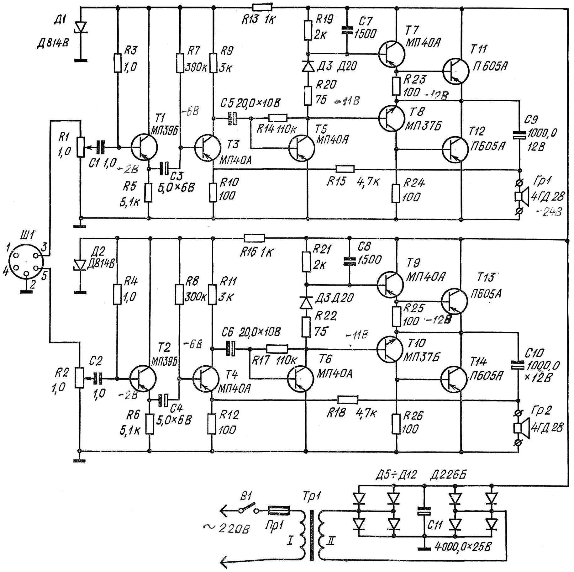
Fig. 1. Schematic diagram of stereo amplifier.
The third stage is also performed according to the scheme with common emitter. The fourth stage of the amplifier is panoinverse and performed on the transistors T7, T8 are of different conductivity type. As a result, since resistors R23, R24 are removed in the same shape, but shifted in phase 180 ka° (bipolar) signals.
When the temperature change and the currents of rest of transistors amp, which can lead to thermal runaway. To reduce the dependence of current temperature in the circuit of the collector of transistor T5 in series with the resistor R20, the diode D3 is included. The forward voltage drop of this diode decreases with increasing temperature (the diode D20 is approximately 2 mV per 1° C), causing a decrease in voltage at the bases of transistors T7 and T8, respectively, at the bases of transistors T11, T12. Quiescent current, therefore, will be stabilized. In the terminal cascade of transistors used П605. They can be replaced with transistors П213—П214, increasing the values of the resistors R23 and R24 to 220 Ohms. To facilitate the thermal regime of the transistors T11, T12 (T13, T14) are mounted on the radiator (Fig. 2).
At the input of each amplifier included volume control (R1 in the “right” channel and R2 — in the “left”). Separate volume controls allows you to relinquish control stereoballs.
To reduce the nonlinear distortion of the amplifier covered by negative feedback: from the output through a resistor R15, a voltage is applied to the emitter circuit of the transistor T3. The diet of the first two cascades of stable (D1). Capacitor C7 prevents the self-excitation of the amplifier at ultrasonic frequencies.
DETAILS of the amplifier applied to the main finish. Exception: power transformer, heat sinks for power transistors, circuit boards, chassis, enclosure and acoustic speakers.
МП40А transistors can be replaced with any of a series МП39—МП42. Instead of the diode D20 can be applied to the diodes D18, Д7А—Д7Ж – Д814В Zener diode can be replaced by a D810 or Д818В.
Electrolytic capacitors — C50-3 (SP — C50-6). Fixed resistors — ML T is 0.5. Nominal values of resistors may vary within ±10%. For example, instead of the resistor 3 kOhm you can use resistors with a nominal value of 2.7 kOhm or 3.3 kOhm. Potentiometers R1 and R2 — SP-1, SP-1A.
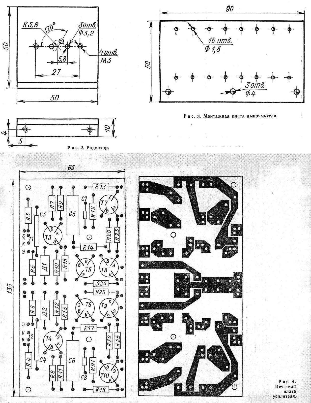
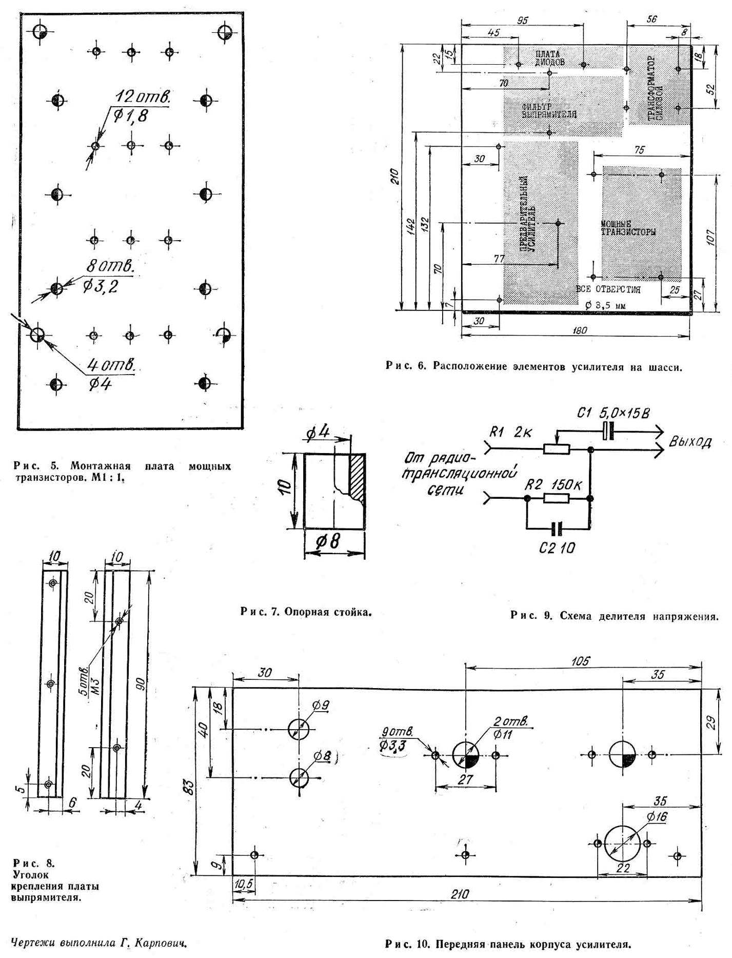
The circuit is mounted on three boards: the rectifier (Fig. 3), amplifier (Fig. 4) and power transistors (Fig. 5). Under the conclusions of parts on the first and third mounting boards pressed petals. Amplifier Board is made of foil Micarta thickness of 1.5 mm.
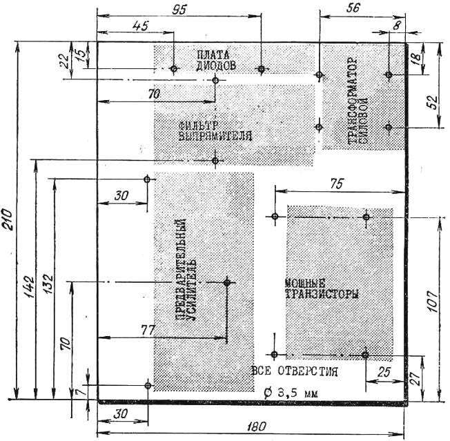
The DESIGN of the amplifier is assembled on a chassis the size of 210X180 mm from sheet 2 mm thick duralumin. Schematically, the arrangement of the circuit elements shown in figure 6. PCB Board and power transistors are attached to the chassis using brass standoffs (Fig. 7). To set up the Board of the rectifier used dural area cross-section 10X10 mm (Fig. 8).
The amplifier is housed in a prefabricated aluminum building. On the front panel (Fig. 10) contains: two separate volume control, on / off switch power indicator network and unified input connector. On the rear panel are jacks for connecting speakers.
Speakers represent the system of closed type, which is equipped with one loudspeaker 4ГД28. The body column glued from plywood 12 mm thick and have dimensions 300X200X120 mm. Rear and front wall are made of the same material and is firmly secured by screws to the housing. The internal volume of the column filled with cotton wool.
To improve sound quality it is advisable to install one high-frequency loudspeaker, for example, of the type 1ГД-3РРЗ. The low frequency loudspeaker is connected in parallel across the capacitor 3 UF.
The loudspeakers and amplifier are covered with plastic foil that imitates valuable breeds of tree. The front panel of the amplifier are painted light nitroenamel.
Handle the volume controls turned on a lathe from hard rubber and polished.
COMMISSIONING starts with a thorough check of correct installation. If the amplifier is assembled correctly and from known-good parts, it immediately begins to work.
If you are not experienced in the installation of such devices it is better to collect the amplifier on the breadboard, to establish it, and then the details transferred to the prepared printed circuit Board.
Correctly assembled amplifier voltage at the electrodes of the transistors should not vary on the concept of more than 10%.
The quality of the test amplifier from the Phono or radio transmission network. In the latter case, should collect the divider (Fig. 9).
V. SHILO, V. YURYSHEV
Recommend to read
 FLOATING TANK, WHICH “DROWNED”
On the fronts of world war II in the fighting military units along with various armored vehicles involved and light tanks. It is known to our T-26, T-60, T-70, the American M3 and M5,...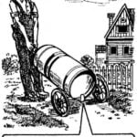 NOT A TRUCK, AND LUCKY
Even a teenager will be able to cope with a large metal flask of water or heavy gas cylinders, driving them to the house without the help of a truck, but only because that's such a...
