
 In most of our schools calls still include the old — fashioned way of push-button attendant or watchman. But this process is not difficult to automate. Proposed device designed for this purpose and may be made in the school radio. The block diagram of the device of the machine shown in figure 1. Electronic digital clock serves at a specified time in the actuator control signals. The actuator enables and disables the programming device, which, in turn, in accordance with the schedule of calls includes internal buzzer and external powerful school bell, feeding him the voltage is 220 V.
Schematic diagram of digital clock with the Executive device is shown in figure 2 For the basis of the scheme is taken from radiokonstruktor “Start 7176”, which added a few additional control buttons. The watch is collected on a large integrated circuit (BIS) К145ИК1901, which can operate in the mode of issuing control signals from the coincidence of the current time with the preset values of two independent registers (the mode “Alarm 1” and “Alarm 2”). To display the time used digital vacuum fluorescent type indicator ИВЛ1 – 7/5. Constant voltage power supply circuit 27. In voltage ~5 V for the filament of the indicator are produced by the mains power supply, consisting of transformer T1, full-wave rectifier diode VD1 and VD2 and parametric stabilizator assembled from Zener diodes VD3 — VD5, resistor R1 and filter capacitors C6, C7.
The Executive device (2) is composed of the VT1 and VT2 transistors, electromagnetic relay K1, diode VD7 and resistors R6 — R11 it Works in the following way. When receiving the control signal from the output 27 of the chip DD1 through a current limiting resistor R6 to the base of transistor VT1, it opens and relay K1. The contacts K1 are closed and 1 is connected in parallel to the transistor VT1 resistor R10, whereby the relay remains on after disconnecting the control signal from the output 27 of the chip. Contacts K1 2 (Fig.4) are closed and include the device software. When receiving the control signal from terminal 28 of the chip at the base of the VT2 transistor will open and sauntered the relay coil K1. Relay will switch off and unplug the device software.
Trimming resistor R11 sets the current, a slightly larger current relays with an open transistor VT1. Resistor R10 is selected so that, when transistor VT1 is closed and the closed contacts K1.1 the current flowing through the relay coil, was a little more current to release the relay.

Fig. 1. The block diagram of the automatic feeding machine of school bells
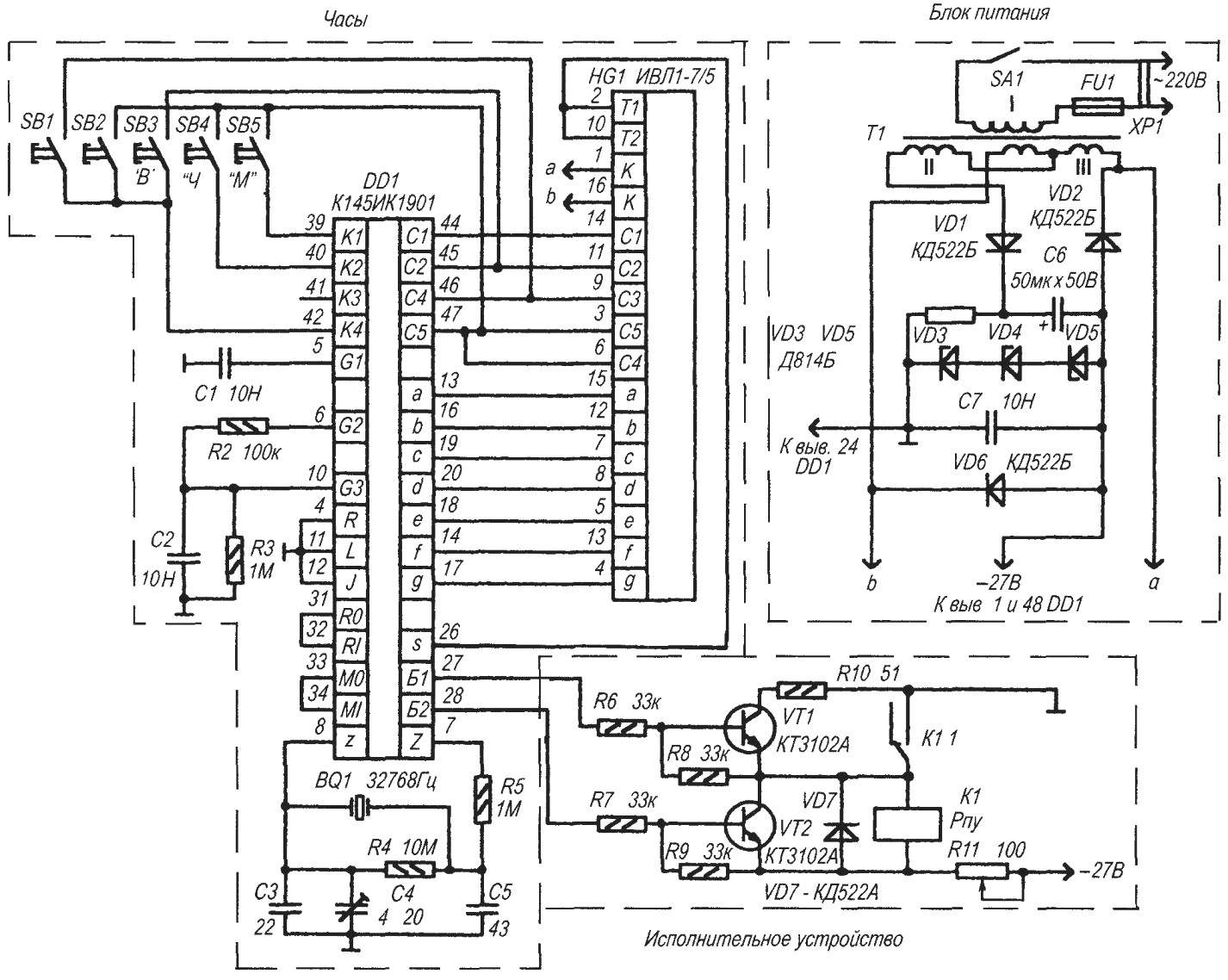
Fig. 2. Circuit diagram of digital clock with the Executive device for supplying calls
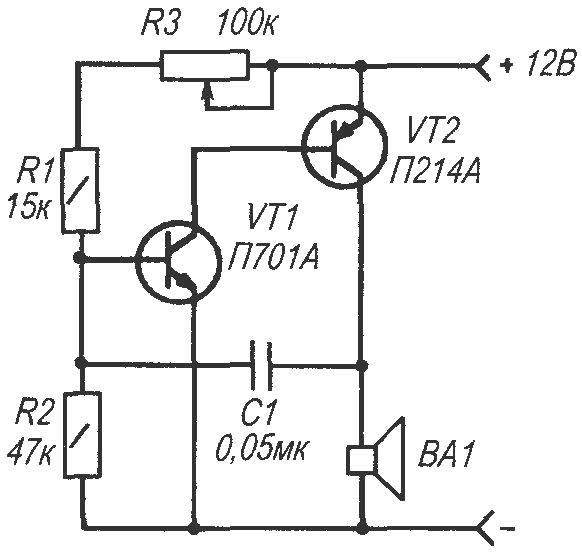
Fig. 3. A circuit diagram of a sound signaling device
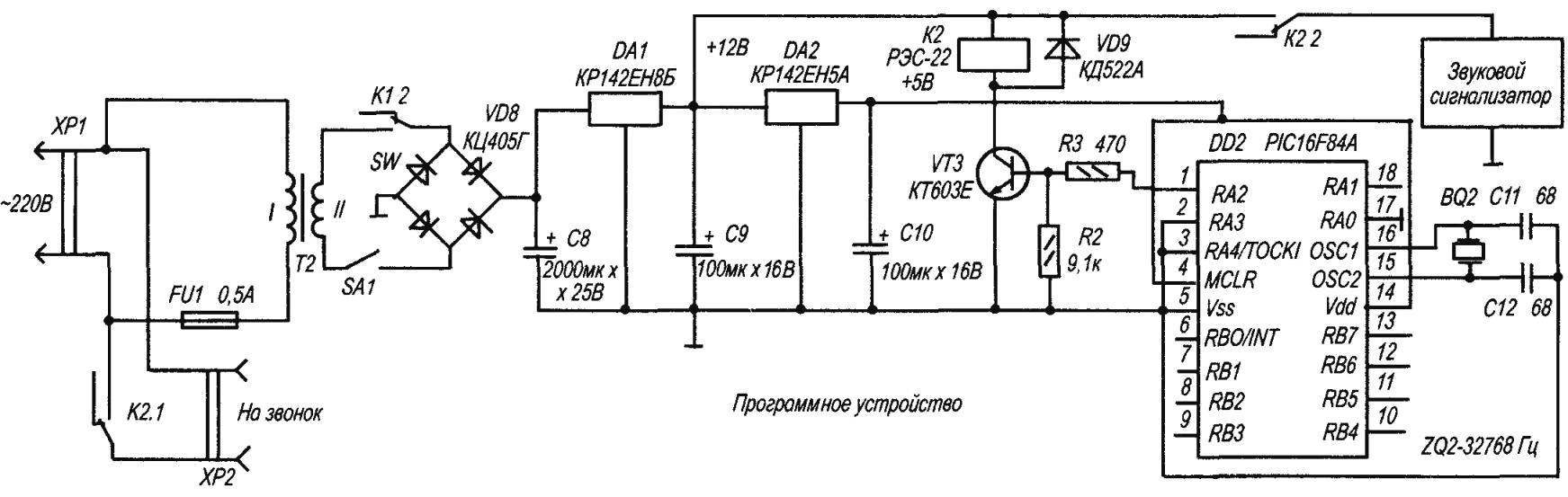
Fig. 4. Electrical schematic software device
Schematic diagram of the software of the device shown in figure 4. The main unit it is a microprocessor-based controller DD2 Microchip type PIC16F84A Microcontroller is programmed (the program control of microcontroller shown below) that at its output RA2 (printin 1) periodically, in accordance with the schedule of calls, there is a high level signal. This signal includes an electromagnetic relay K2. Relay K2 contacts K2 your 1. includes a large school bell, and the contacts K2 2 — buzzer located inside the machine Internal buzzer is mainly used to configure and test the operation of the machine.
Power supply the software consists of step-down transformer T2, diode bridge VD8, filter capacitors C8-C10 and chip stabilizer DA1, DA2. Chip DA1 stabilizes the DC voltage of 12V which feeds the relay K2 and the buzzer. With stabilizer DA2 voltage of +5V is supplied to the microcontroller DD2.
The program that controls the operation of the microcontroller.
(Language — assembler MPASM Microchip)
The MACHINE CALLS FOR 7 LESSONS; QUARTZ FREQUENCY 32,768 Hz
list p=16F84A #include <p16F84A inc>_
CONFIG 3FF0H
ADDRESS ASSIGNMENT OF CELLS TO VARIABLES
st1 EQU Ojos loop variable st2 EQU OxOD, the loop variable st3 EQU 0x10, a loop variable st4 EQU 0x12, the variable cycle.
INICIALIZACIA
ORG 0x000 ;reset vector of the processor, the starting address of the cirf PORTA .cleared output latches of port A clrf invertion PORTB ;and port bsf STATUS,RP0 .incorporated Bank 1 movlw b’00011001′ set up port a, lines RA0, RA3, RA4 input, movwf TRIS .the rest of the output movlw b’00011111′ set up port, line, RB5, RB6, RB7 for output movwf TRISB others to enter OPTION_ bcf REG, 7, included pull-up resistors bcf STATUS,RP0 included Bank 0.
MAIN APPLICATION
call beep, call sound call call min45, call a 45-minute time delay call beep, sound call call min10,10-minute delay call beep .call call min45, 45 min delay call beep ;call call mini 0, delay-10 min call beep .call call min45 .a delay of 45 min call beep .call call min 10 .a delay of 10 min call min5; and so forth min45 call call beep call beep call min10 min45 call call beep call beep call min10 min45 call call beep call beep call min10 min45 call call beep call beep.
ROUTINES
routine five minutes min5 delay movlw OxFF .set initial value movwf st1 .variable of the outer loop cyclel movlw OxFO .set initial value of the variable movwf st2 ;the first nested loop cycle2 movlw Ojos set initial value of the variable movwf st3 .the second nested loop st3 decfsz cycle3, f .decrement variable st3=st3-1 goto cycle3 .if st3 is not zero, repeat decfsz decrement st2, f .decrement variable st2=st2-1 goto cycle2 ,if st2 is not zero, repeat decfsz decrement st1, f ;decrement variable st1=st1-1 goto cyclel ;if st1 is not zero, repeat decrement return .a return from a subroutine
.routine ten-minute delay mini 0 movlw 0x02 movwf call min5 min10_1 st4 st4 decfsz, goto f min10_1 return .subroutine sorokapyatiletnyaya delay
min45 st4 movlw 0x09 movwf call decfsz min45_1 min5 st4, f got min45_1 return
programme on beep beep bsf PORTA, 1 setting 1 output RA1 bsf PORTA,2 setup 1 from the output RA2 movlw 0x05 movfw ciclel st3 movlw OxFF movwf decfsz st4 st4 cicle2,f goto decfsz goto st3 cicle2 ciclel bcf PORTA, 1 is set to 0 at pin RA1 bcf PORTA, a setting of 0 on pin RA2 return end
Program in machine language an assembler is developed and compiled (converted to machine code) by using the integrated development environment MPLAB [1] and entered into the microcontroller by the programmer Sl-Prog [3] and supports the it program PonyProg [3] It can be easily modified to fit any schedule
The design of the device
The device is mounted on five printed circuit boards, which are placed in steel casing with dimensions of 300x200x85 mm housing Cover serving as a front panel of the device, made of sheet aluminum 2 mm thick. it is cut a window for the digital display. Fee hours together with the indicator attached on the inside of the front panel, it also installed a Board with microcontroller and dynamic head On the front panel below the display are five buttons. Buttons SB4 “setting the clock” (“H”) and SB5 “SETTING MINUTES” (“M”) are configured the display modes the current time and the time the operation of the programming device With the buttons SB1 “on” SB2 and the “OFF PROGRAM” the machine switches to the setting mode time on and off software the device. Button SB3 “TIME” (C) returns the clock mode indications of the current time. On the front panel also has a switch SA1 is “OFF PROGRAM”, which disables the device software on weekends and during school holidays
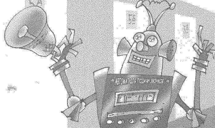
At the bottom of the fixed housing Board Executive unit hours, power supply and transformers On the rear of the device houses the socket 2 for connecting an external powerful call and the fuse FU1 General view of the device shown in the Intro
ROGOZHIN, Saransk
Recommend to read
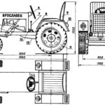 MINI TRACTOR STUDENT
No, the headline is not a hoax. And not even the "joint work of members Kota, led by a talented teacher and organizer of technical creativity of rural children". It is a workable... A WEAPON OF LAST HOPE
the SPECIAL ASSAULT AIRCRAFT of JAPAN. By early 1945, the Japanese military-political leadership was aware that sooner or later we should expect the allied invasion to the territory of...
