 My thyristor voltage regulator (THREE) is easy in manufacture and adjustment, linearity regulation and high power output — 200 watts without heatsink and 1000 watt radiator cooling area 50 cm2.
When you enable TRN half wave positive supply 220 volt voltage runs through an electrical circuit VD2RЗR4 and charges the capacitor C2. As soon as Uзаряда will exceed the switching voltage of the thyristor VS2, the latter will open and let part of the positive half-wave to the load. VD4R5 protects the circuit VS2 via the current control.
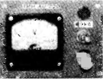
Changing the total resistance of R4, you can get adjustable (40 to 220) output voltage for direct measurement of which is designed with indicating voltmeter PV1. Indicator lamp HL1 is designed to monitor the mains voltage and the integrity of the fuses FU1 and FU2.
It THREE cheap and common type of MBM. For R1 ,R2 and R5 can be applied MLT-0,25. In the place of R3 the good work MLT-0,5 (MLT-1). The variable resistance suitable JS1. Voltmeter Ts4201-type or equivalent, designed for 250 VAC. Indicated on the wiring diagram the diodes can be replaced by the less powerful, e.g. КД102Б or КД105Б. Thyristor with a reverse voltage of at least 300 To, say, КУ202Н or КУ202Л. And if you want to use TPH with load not exceeding 350 watts, it can be applied КУ201Л.
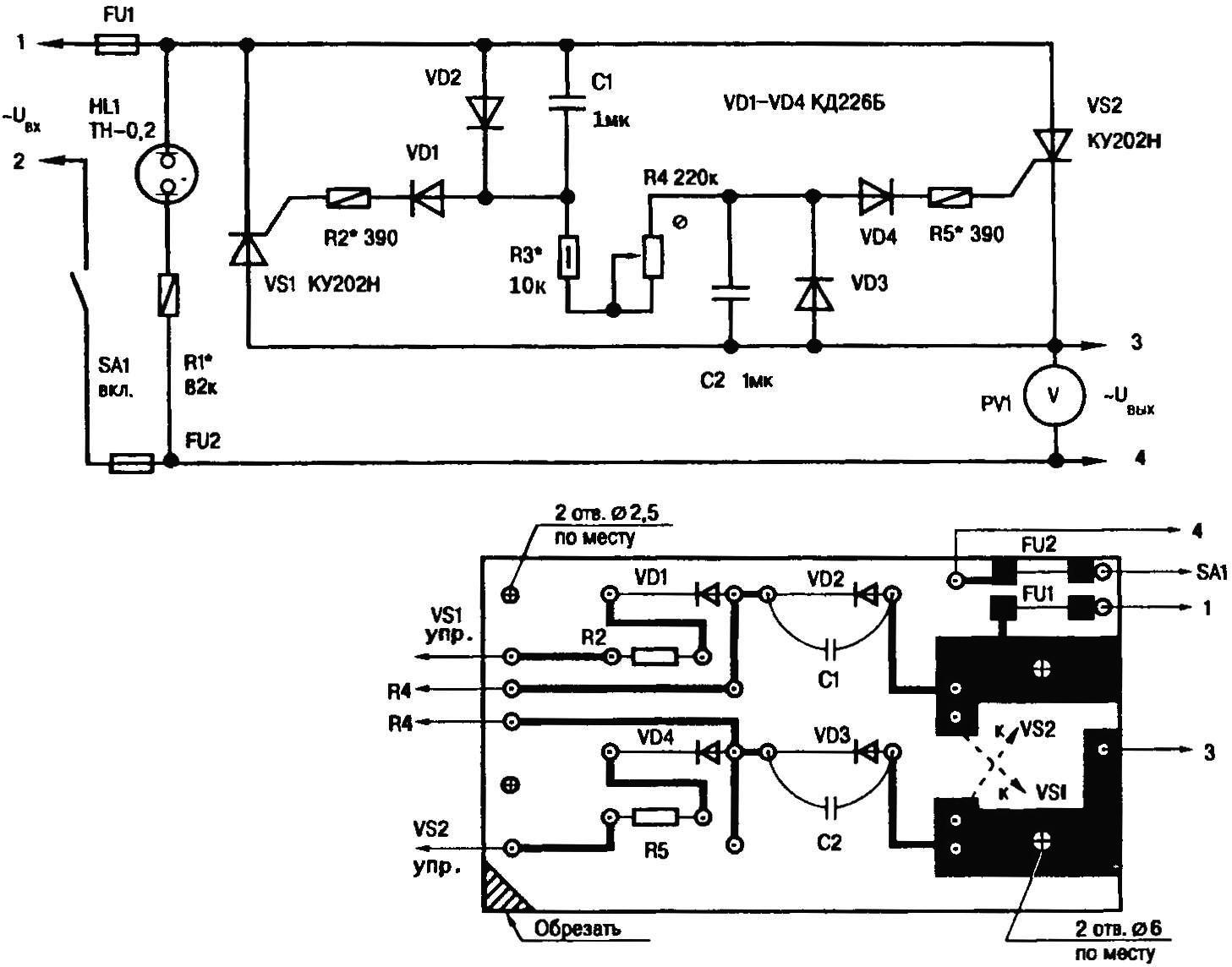
A circuit diagram and a printed circuit Board, thyristor voltage regulator
Neon lamp HL1 type TN-0,2. Fuses are selected based on the operation of the device with a maximum current consumption. If the load is a motor (for example, similar to what is used in hand drills), Iex. = 0,5…0,6 Istart.
TRN is better to establish on a temporary circuit Board. Is 390-kilimnik R2 and R5 to first solder a 1-calomnie resistors. Then, reducing the resistance of R4 and R3, to minimize the voltage drop on the VS1, VS2.
Resistors R2, R5 limit the current of the thyristors. They are selected at the maximum power in the load. Even if the establishment is not permitted to increase the current control thyristor 100 mA max.
After adjusting all the elements of an electrical circuit are transferred to the PCB dimensions 100x50x2,5 mm of one-sided foil fiberglass.
S. BABENKO, Moscow region
Recommend to read
 COMPACTS BALONEY
In the preparation of the apartment for the winter period suggest to seal the frame as it has long been I do. It does not require neither paper nor CPA, nm foam or wool. Only need window... THE USE FOR ONE
"Headphone for stereo? This is too much, can mind reader. — How can provide high quality playback of regular head phones? After all, this requires a wide range of frequencies, a slight...
