WATERING MACHINE

WATERING MACHINEMany plants, like tomatoes, during its growth and fruiting require a lot of moisture, so they often have to be watered, especially in hot season. The proposed machine will help you save valuable time and eliminate the need to be constantly “tethered” to their Pets. Just turn on the power and set the clock correct time of watering. The device is simple to manufacture, and at the same time it is reliable in operation.

The machine consists of a power supply, an electro-mechanical clock “Slava” (or such others having an alarm clock), time relay, sensor and humidity controller, and mechanism for controlling the refilling of tank and watering.
 
Let us dwell on each of these nodes. Electro-mechanical watches are powered by element 373 voltage of 1.5 V. It lasts for 12 months. The machine clock is used for the initial inclusion. Contacts are used, causing the alarm. The end of the wire 1 (Fig. 1) is connected to the body of the mechanism, and the end of the 2 — to arm the alarm, in the place where you soldered the wire of a buzzer. To save energy, the buzzer should be turned off.
 
The time relay is assembled on transistors /T1 /T2, and serves to lock contact hours and also to adjust the time of watering. It is set by the variable resistor 133. Note that the smallest time slot — 3 min, as the contact hours remain closed during this period, however, such exposure to normal irrigation is not enough.
Humidity controller assembled transistors /TK /T4; consists of sensor B1 and the electronic unit. The sensor consists of two plates of stainless steel, of a width of 20-25 mm. their Length depends on the depth of soil moisture, and the distance between the plates are selected experimentally — largely it depends on the type of soil. The splices with the sensor must be covered with waterproof paint. The trigger level for the automatic devices set by the variable resistor 137.
 
The triggering sensitivity of the device limit (to prevent waterlogged soil) by the bypass sensor is a variable resistor Я9. You can disable it with a toggle switch БА2.
 
The power supply can be provided by a car battery with a capacity of 50/55 A/h or a network rectifier (Fig. 2).
 
Water-feeding device (Fig. 3) consists of pipes, pre-tap, tank, traction, magnetic relays, faucet, watering pipes.
 
Fig. 1. Schematic diagram of automatic devices
 
Fig. 1. Schematic diagram of the automatic device.
 
Fig. 2. Fundamental . the scheme of power supply
 
Fig. 2. Fundamental . the scheme of the power supply.
 
R and p. 3. Connection diagram of the water supply device
 
R and S. 3. Connection diagram water-feeding device:
1 — pipe, 2 — pre-tap 3 — mounting nut 4 — ball valve 5 — reservoir 6 — nuts and washers securing the pipe to the tank, 7 — rubber ring-gasket 8 — the traction relay, 9 — front fastening of the traction relay, 10 —valve, 11 — recoil, 12 — mounting bracket return springs, the 13 water pipe, 14 — tubes-plugs, 15 — pull plate, 16 — gasket, float valve.

 
Fig. 4. Diagram of the mechanism for opening and closing the faucet
 
Fig. 4. Diagram of the mechanism for opening and closing the faucet:
1 — magnetic core, 2 — winding traction relay, 3 — the case of the traction relay 4 — pull rod 5 — axis mounting a traction stud to the drive plate, 6 — power plate 7 — valve, 8 — return spring 9 — strut mounting of the return spring, 10 — handle, 11 —mounting screw.

 
R and p. 5. Relay racks and springs. R and S. 6. Drawbar
 
R and S. 5. Relay racks and springs. R and S. 6. Drawbar.
 
Pipes have internal 0 20-25 mm, but it depends on the area of irrigation. The crane of any suitable inner and outer diameter. Float valve from the cistern, is fixed at the top of the reservoir using the mounting nut, which screws onto the pipe. Inside it is screwed through the spacer shank float valve.
 
Reservoir — an ordinary 200 litre drums. You can use any other: capacity depends on the water area. The pipe is connected to the reservoir, which is drilled a hole in the bottom of the same diameter as the diameter of the pipe. At its outer diameter cut thread and then screwed the first nut that should be on the outside of the tank; put a washer and the rubber ring. Then the tube threaded portion is inserted into a hole drilled into the bottom of the tank, place a second rubber ring with washer and tighten the second nut.
 
After the tube attached to the reservoir, install the faucet. It needs to be such that by rotating the handle 90° to open.
 
When the faucet is installed, proceed to the fastening of irrigation pipes having internal 0 10-15 mm; with one hand they have drilled two rows of holes 0 2 mm. Each such pipe have over watered furrow, holding the level. On one end of the pipe should be plugged.
 
Such pipes in the machine can be as much as necessary; but this should increase the capacity of the tank, increase pipe diameter tap. If filling one float valve is not enough, one should add one, connecting it in parallel.
 
The tank shall be at a height of 1 to 1.5 m above the irrigation pipes. For this purpose it is mounted on a special welded stand; but you can use an old table, drilled in the lid hole for the pipe.
 
Irrigation pipe is placed on stands, or, if possible, of the suspension, putting on the level. And they should be tapped holes up. This is to ensure that watering is carried out evenly. The fact that watering will not begin until the pipe is not filled over the entire length. Here’s what happens: water enters the tube, filling it completely, creating the pressure under which the via is drilled in the tube hole it starts to pour evenly over the entire length, thereby providing a watering of the entire area.
 
A solenoid switch used in the machine, can be used from cars ZAZ-968 — allowing you to pull the starter gear.
 
How machine works? When it comes to watering, set the clock hand of the clock, the contacts are closed. The current from the power source through closed switch ЅА1 and contact a few (hours) is applied to the time relay, and it works. The contacts K1.1, serving for self-starting, open, K1.2 are closed, thereby ensuring locking of the contact hours system, and K1.3 includes a humidity controller. The latter is necessary for the protection of contact hours at the time of inclusion, because they are not designed for a current which consumes the traction relay.
 
The resistance of dry soil is high, so the humidity controller fails, and the current through the normally closed contacts of K2.1 and K2.2 is supplied to the traction relay. It is triggered, opens the valve and simultaneously stretches the return spring. The water supplied to the watering pipe: the irrigation. With the decrease of the water level in the reservoir float valve opens and the water enters the tank. When it reaches a predetermined level, the float valve closes and filling stops.
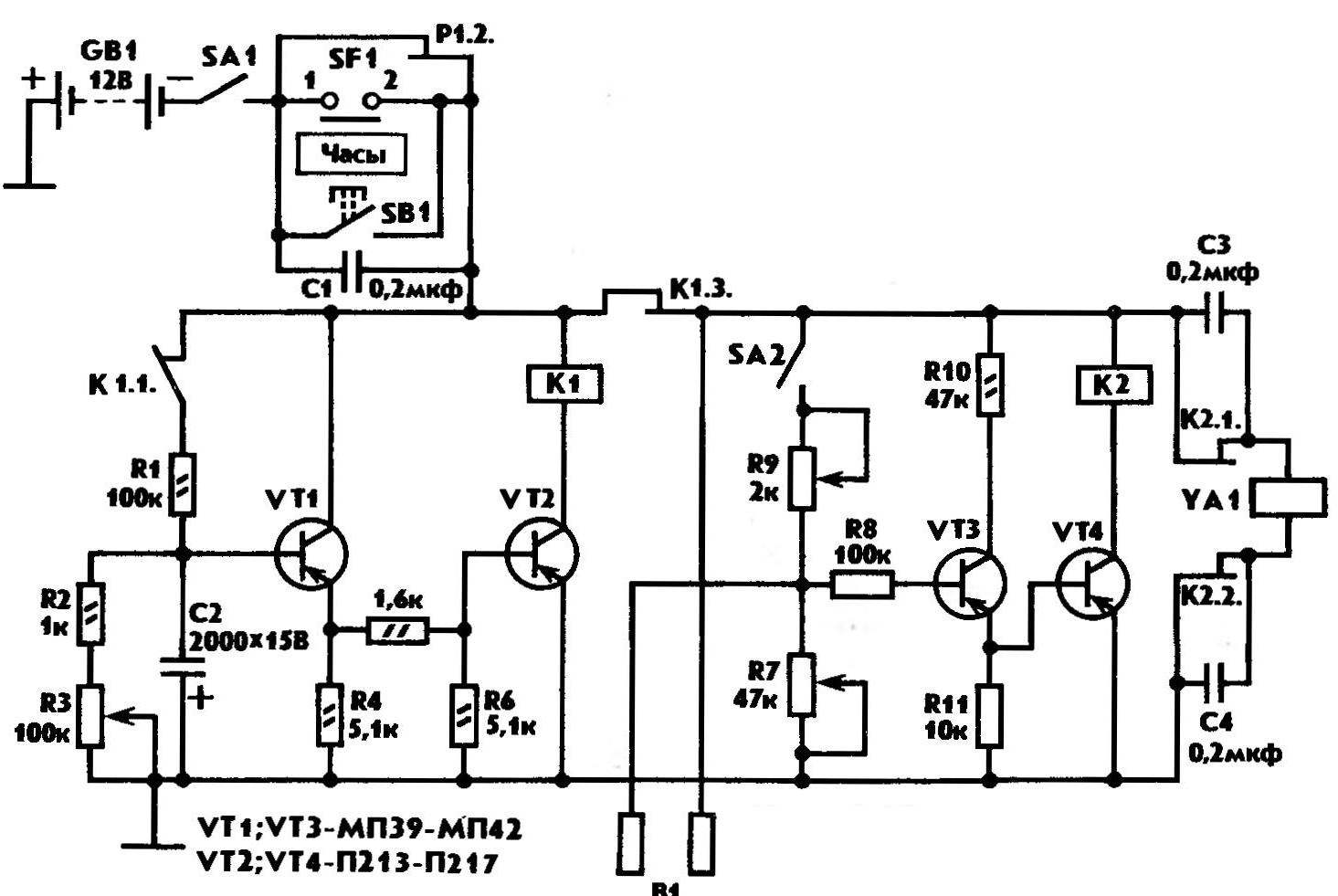
The plot is watered down to predetermined humidity. Humidity controller is triggered, and the relay K2 opens its contact pair K2.1 and K2.2. Stops the supply of power to the traction relay. The recoil spring is compressed, closes the valve and leads to the original position solenoid: watering stops. The device may repeat the above operation several times within one inclusion. Upon expiration of the time allotted to the device, the contact K1.2 opens. Food stops, the machine switches off.
 
The device can launch at any time. You just need to click on 2…3 button SBI, is connected in parallel to contacts hours.
 
The scheme of connection opening and closing valve of the mechanism shown in figure 4. Length of the traction plate depends on type of used crane, and the power of the traction relay. Approximate length: 45 mm, width 10 mm, thickness 3 mm. A solenoid switch is mounted on the metal plate-rack, the bent radius on both ends. One of them has the same diameter, which is the case of the traction relay, the other — as feed pipe. Such a design has the strut, which is geared recoil. Types of racks are shown in figure 5.
 
The device can be applied and improvised traction relay. The cut shown in figure 4. These windings and the dimensions of the parts given below. Device drawbar — figure 6.
 
Now about the device used in detail. The data of the resistors and capacitors shown in the diagram (Fig. 1), the button — bell. Transistors: /T1, VT2 — low-power, low-frequency, p-n-p type, VT3, VT4 — any larger or medium-power, R-p-R type (for example, a series KT816).
 
As a K1 you can apply relay RES—22 (passport RF4. 560.163) or other similar relays (one with normally closed pair of contacts and two normally open), reliably trigger voltage of 10-12 V.
 
The traction relay has two windings. One is used to obtain the stationary magnet and the second to move the traction rod. They are connected in parallel. You should consider the fact that the winding must be wound in different directions. The winding can be wound in one direction, but then the first end must be connected to the beginning of the second, and the beginning to the end of the second. Each winding comprises at 5720 turns. Winding is wound with a wire PEL-1 to 0.5.
 
The enclosure must be made of non-magnetic material, brass or aluminum.
 
Move drawbar — 40 mm, diameter 30 mm, length 90 mm. To facilitate core of its nasal part worn down to 10 mm, it is propyl depth of 10 mm, a width of 3-4 mm. It is used for connecting the rod with the pulling plate.
 
The transformer of the power supply is wound on the core Network Ш25х71 mm. coil, designed for 220 V, contains 550 turns of wire PEL-1 0.5 (127 V — 320 turns of the same wire). The secondary winding is designed for a voltage of 12 V and contains 30 turns of PEL-1 to 0.9. Windings are isolated from each other cloth insulating tape, or varnished cloth. The assembled rectifier diode series Д242. The filter capacitor (C2) has a capacity of 1000— 2000 UF, the voltage of 12 V.
 
The power supply can be placed in a common housing with a gun, and in a separate case.
 
If the correct Assembly of the establishing device is configured for the desired percentage of moisture watered plot. May experience some difficulties when setting up the mechanism for opening and closing the valve. In this case, you need to pick up the return spring at which the solenoid will begin to operate normally. Instead of the spring can be applied to ordinary, quite elastic, the elastic, able to ensure reliable operation of the mechanism.
 
It is particularly convenient to use this machine in greenhouses and greenhouses. Applying the system of automatic ventilation, they can be made fully automated.
 
Yuri YUDIN, g. Safonovo, Smolensk region.

Recommend to read

  • DROP BY DROP — PEN!DROP BY DROP — PEN!
    After working with epoxy, always remains a small quantity of it, which can be used for the manufacture of arms to the small tool, such as needle files. To put on them a big "drop" to...
  • START of CLASS A1START of CLASS A1
    The unusual design of bearing areas — that is the main distinguishing feature of the proposed model glider. Their advantage in ease of manufacture. The absence of cut from the sheet...