
 Probably you are familiar with simple electrical device for training “the steadiness of the hand” — a metal panel with a narrow winding slot, along which, without touching its edges, it is necessary to hold the pivot-pin. One careless touch probe to the edge and flashes the warning light. Such devices form the basis of the various attractions and special equipment. This principle is valid for our slot machine.
The game involves two. The challenge was to be the first to hold the probe without touching the slots in the panel, from “Start” to “Finish”.
Before each of the players is console size 200X100X100 mm (Fig. 1). Remotes with four-wire cable through the connectors connect to the control panel and alarm (Fig. 2).
K1.2 closes the power circuit of the H1 bulb, illuminating the scoreboard, “Start”: the machine is ready to work.
The game starts by pressing the button S2 “start” on the remote control and alarm. When capacitor C2 is charged from the power source, the transistor V5. Relay K1 actuates, disengaging its contacts K1.1 the control units of the actions of the players, and K1.2 — lamp H1 display “Start”.
When you release the button S2, the capacitor C2 discharges through R1 resistor and through the circuit: R3, shift of the “emitter-base” V5 R2. After 10-20 with the capacitor C2 discharged, and the transistor V5 is locked again. Relay K1 opens its contacts, and on the remote control flashes display “Start” command to start a contest.
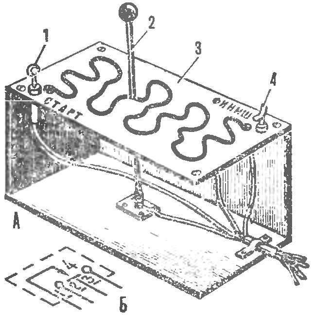
Fig. 1. Remote player:
a — design panel; b — the symbol on the schematic diagram; 1 — focus-contact “Start” 2 — rod-probe 3 — metal pad, 4 — point blank-contact “Finish”.
At this time, if the probe of the first player rests on the stop-contact “Start,” voltage flows to the relay coil K2. It is triggered and your contacts K2.1 cambiocorsa, and K2.2 includes the green lamp H2 “Start” of the first player. The Contact K2.3 prepares for the inclusion of a relay coil K4. Thus, if the command “Start” the lamp of the first player s caught fire, it needs to return the probe to its original position only after actuation of a light signal to start the movement of the probe along the slot.
Touch the probe to the edge of the slot causes the relay circuit, and its contact K3.1 disables about the ball of K2. The green led H2 goes out, and the player needs to return the probe to its original position, to start moving first. This occurs whenever the probe touches the edge of the slot.
After the probe along the slot without error, plays for emphasis-touch “Finish”. And, if he is ahead of his opponent, the contact K7.3 remains closed and the voltage supplied to the relay coil K4 (K2.3 is also closed). It is activated its contacts K4.1 is locked, and K4.2 includes a red signal lamp H3 “finish” on the control panel and alarm. Contact K4.3 opens the circuit of the power relay coil K7 to the control unit of the actions of the second player. Now the red warning light H5 “Finish” this player will not be included, even if it will cause your probe to the finish without mistakes: he was late and therefore lost.
Now suppose that the first player will finish last. In this case, the contact K7.3 is disconnected (relay K7 work before, when the probe of the second player closes the stop-contact “Finish”).
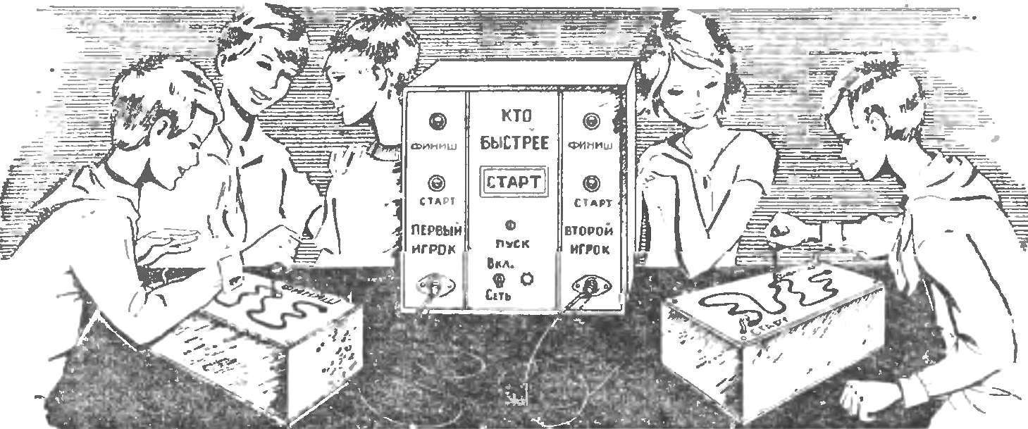
Fig. 2. Control panel and alarm and remote players.
After the game, the opponents return the probes to “Start” and press the “start” button. However, as we saw on, unlocked the transistor V5, and relay K1, actuating its contact K1.1 disables all other relays, bringing the device to its original state. 10-20 with team flash “Start” the game can start again.
The design of the machine is based on publicly available parts and materials. Diodes series D226, D7, transistor П201—П203; resistors aircraft or MLT; electrolytic capacitors of any type with an operating voltage of not less than 50 V. K1 — relay ILV (passport RF4. 530. 810), K2-K7 RES-22 (passport RF4. 500. 131). Lamp LN 3.5 V, 0.28 A, S1 — switch TP1-2, S2 — button K1; X1 and x2 — and five-pole connectors SSHZ.
The power transformer has a core made of plates Ш20, typed in the package with a thickness of 45 mm. the Primary winding has 1320 turns of wire PEL of 0.31; winding II — 20 turns of wire PEL of 1.2; winding III — 180 turns of wire PEL of 0.62.
Power supply, time relay and the solenoid are placed on a horizontal metal chassis, and the controls and display on the vertical bar. Chassis and panel mounted in a metal or plastic case the size 220X220X160 mm.
At the helm of the players front panel made of sheet aluminum with a thickness of 1,5—2 mm. they cut a winding slot width of 3.5—5 mm.
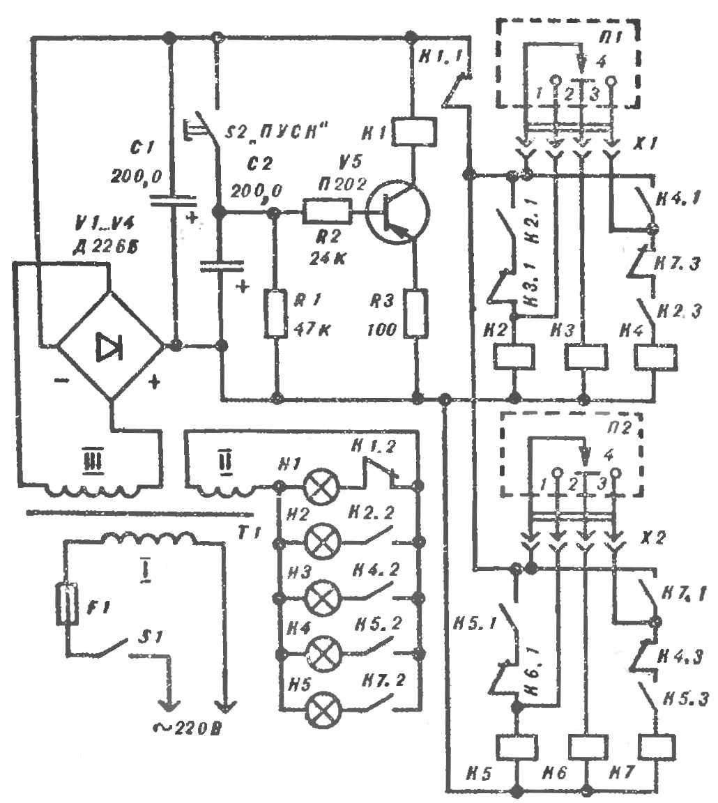
Fig. 3. Schematic diagram of the slot machine.
Stem-the probe is made of copper wire Ø 2,5—3,5 mm. On the upper end of the rod reinforced plastic ball-shaped handle, and its lower end attached to the base panel via a flexible helical spring, acting as a hinge. This ensures good electrical contact (see Fig. 1). From the same copper wire made stops-contacts “Start” and “Finish”. They can be arranged not above the bar, for greater clarity, is shown in figure 1, and under it, inside the console.
In establishing the machine does not need: with proper connection of all components and parts it will work immediately after inclusion in the network.
In conclusion, a few tips for those who want to build a gaming machine. First of all the metal panels on the consoles, players can make removable and machine supply with set of interchangeable panels with slits of different width and complexity: from the simple and wide — for beginners to advanced and narrow — experienced players.
The game can participate and 3-4. This will require additional remotes, and a corresponding number of control units of action. At the same time increase the control panel and alarm automatic.
And finally, you can equip a remote control and alarm counters, fixing the winnings of players. Electromagnetic counters SB-1M/100 must be connected to the power supply via the additional contact pair of the relay K4 and K7.
D. can be visited, candidate of pedagogical Sciences, Sverdlovsk, Russia
Recommend to read
 TRAILER-“THE LIMO
 COMPRESSOR MIX
Dear "Modelist-Konstruktor"! In issue No. 9 for 2004 of your magazine, a material was published about a compressor I made based on a motor-compressor from an old refrigerator. I used it...
