The device, made on thyristors, there is an obvious advantage. If this is enabled the control pulse, the thyristor remains in this state until while they will not remove power. In short, at least enough for a moment to press the button and release it will turn on the corresponding lamp, which can be redeemed only with the help of a special button “Reset”.
Enough momentarily press button S1 or S2 (Fig. 6), to the control electrode of thyristor V1 (V2) enters the opening voltage of the battery and the lamp H1 or H2 is ignited.
Fig. 6. Playing on the thyristors.
Fig. 7. The chassis and casing.
Fig. 8. Wiring diagram of a third variant of the game.
Fig. 9. RS-trigger on TTL.
Fig. 10. Playing in TTL.
To reset signals turn off the switch S5 supply voltage with thyristors: then they will return to their original closed state. The same operation is carried out Z button located on the panel of judges in conjunction with the S4 button (“start”). When the contact S battery G1 is the two parallel resistors RZ, R4, and both thyristor are completely disconnected: the lamp H1 or H2 goes out.
The device is assembled in the H-shaped chassis made of three boards and retinectomy closed casing (see Fig. 7).
Lamp and button players painted respectively in red and green. Starting light is white. The installation is made on the “studs” hinged manner (Fig. 8).
The rules of the game “Who is faster?” is simple. Two players sit down at the table and everyone takes your button. The judge gives the command “Ready” and after a while presses the “Start” button. Lights white bulb H3. On this signal the players push their buttons. The one who will light the bulb, wins 2 points. But if any of the players press the button until “Start” signal, he receives one penalty point.
Option IV — on-chip TTL. The same game can be built on a more modern components — integrated logical chips, for example, К155ЛАЗ (К1ЛБ553).
It is based on a simple RS-trigger executed on two logical elements 2I-NOT (Fig. 9). When keys S1 and S2 are closed, both inputs of the trigger there is a logical “0” and outputs a logical “1”: lamps H1 and H2 do not burn. If one of the keys, for example S1 will be opened before the other, on the upper input trigger will be a logical “1” and output logic “0”. As a result, light turns on N1. Now the state of the switch S2 will not influence the trigger and the second indicator H2. you can’t light until the key S1 is open. If the first will open the switch S2, the lamp will light N2 and the influence of key S1 will be eliminated.
In the initial state of the trigger circuit simultaneous return of both keys.
Version of the game on the chip is presented in figure 10. Can play simultaneously two pairs of players (the keys S1,S3 and S2, S5). The command “Start” gives the judge by clicking on the button S4. Light the lamp H1. Since the low-power chip, used for indication LEDs B1—B4 with current-limiting resistors R3, R4, R7, R8.
The device works well at a voltage of SV, so it have enough power two dry cells of any type or one battery 3336L.
Game design and programming buttons S1—S5 can be any.
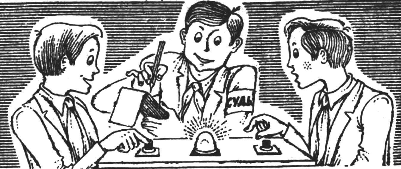
 Our magazine has already told about this exciting game, made on the electromagnetic relay (see “M-K” №1, 1976). And today hams instead of contact devices are widely used in their structures with modern elements as transistors, thyristors, LEDs, integrated circuits. New versions of the game “Who is faster?” with the use of such devices and readers.