 When 25 years ago on the pages of Newspapers and magazines began to appear about the creation of an electronic cybernetic machines are able to play dominoes, checkers, chess and other games, readers in different ways embraced the news. Alone, tossing up her hands in astonishment, and said, “just Think! What came to technique!” Other, moderately severe, people shrugged their shoulders: “Do scientists have nothing better to do?” “What are you — objected to them and others, not so serious, — let them enjoy themselves. It is necessary for scientists to have a rest after hard work”.
Were unaware that, and another, and third that the development and construction of playing slot machines is very important, as the creation of advanced gaming systems opens wide possibilities of electronic technology for the solution of many economic problems.
Now other times. It’s hardly a surprise today, a message about playing a new cybernetic machine. In our days, designing simple playing machines began to successfully engage even a young technology. It’s so fascinating: their hands to build a smart machine that can beat a human associate.
Usually the programme of the games executed by the slot machines are divided into combinatorial and strategic. First, the uncertainty of outcome associated with plenty of different options (combinations), which sorted the players in search of a better turn. In games of this kind for one of the participants in advance there is a set of correct moves leading to the win. Therefore, the second player is obviously doomed to failure.
In the strategic games of uncertainty of outcome due to the fact that each of the participants, deciding about the choice of the next move, not know what course did (or will do) the enemy. In such games to provide in advance all the winning options impossible. So the strategic plan is exciting, with a deep logical content. They wins the most clever and astute strategist.
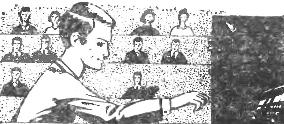
Cybernetic device (Fig. 1) able to adhere to the optimal mixed strategy, designed to play “Believe it or not”. Its essence consists in the following. In the urn two balls: red and green. Player a takes randomly one of them. Player B this procedure does not see. For the red ball relies one point. When you will come across a green ball, then he can say that she took a red, and if the opponent believes will get one point. However, there is a risk that if the deception is discovered, But hand B two points. Sat And do the red ball, two points will give B. Therefore, in this case the safest way out is to admit that you pulled a green ball And give the opponent one point.
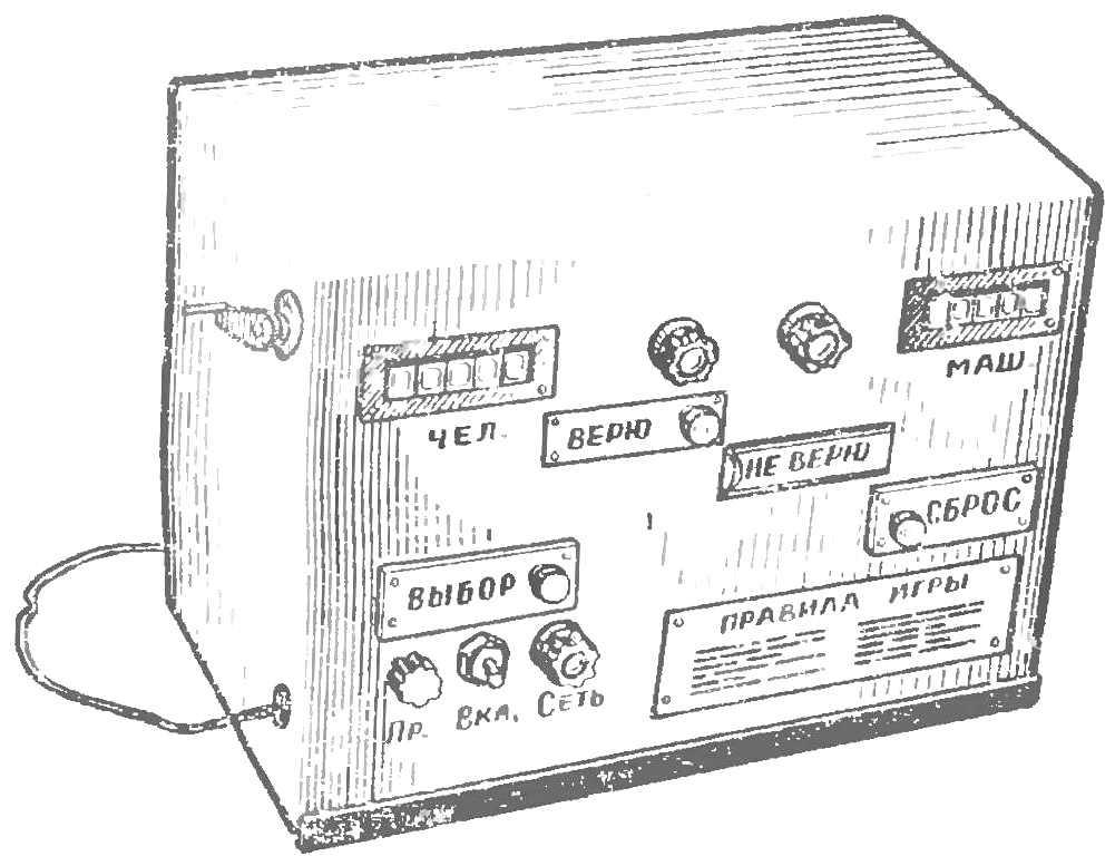
Fig. 1. The appearance of the machine “Believe it or not”.
Of the rules of the game shows that player A has two pure strategies: A1 A2 cheat and not to cheat. Player B has also two strategies: B1 believe B2 — not to believe. In game theory it is proved that the strategy of the first player is optimal if pure strategies A1 and A2 are alternated randomly, and A2 is used twice as often as A1 (i.e., in the ratio A1 : A2 = 1 : 2). Therefore, if the behavior of the first player will match that of the best strategy, he will win more often than player B, and the match, consisting of many parties, will end in his favor.
In the game “Believe it or not” with the functions of the player And successfully can handle a simple cybernetic device. Of course, have to modify the game, because the machine will not be able to distinguish the balls by color. But they can be replaced by two lights, red and green. What kind of light bulbs are enabled, the machine is easy to “understand.”
When player a takes from the urn one of the balls he is equally likely to take any of them. Replacing bulbs bulbs you need to provide in car device, such as a polarized electromagnetic relay which includes at random with equal probability each of the bulbs. In this relay the direction of deviation of the armature depends on the direction of the current in the winding. If you connect the relay coil to the AC power source (Fig. 2), the armature will vibrate with a frequency of the network deviates to one direction and then the other; cut-off current (when the button is released KN) anchor is equally likely to stay in the right and left position respectively, will light one of the bulbs connected to the current source through the Executive relay contacts.
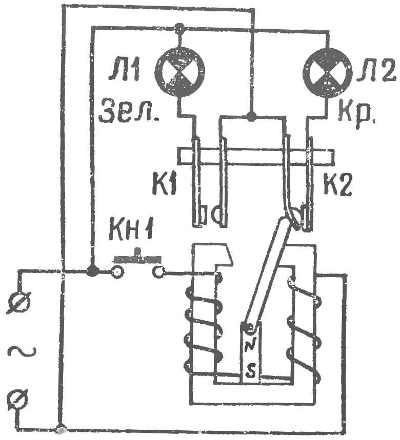
Fig. 2. Variator random selection
Now need to program the behavior of the player And the machine. How to make it randomly in the ratio 1 : 2 alternated their pure strategy?
This task is also not hard to put on a simple Electromechanical device. Part of the surface (sector 120°) a rotating plastic disk pressed to his stationary contact brush coated copper foil (Fig. For). If this disk from time to time to stop, contact “brush disc” will conduct electric current only in one third of all cases — when the brush is pressed against the metal foil.
Copper 120-degree sector can be divided into several smaller sectors, symmetrically located on the plastic disc (Fig. 3b). If now the electrical circuit in series with the brush and disk to enable the winding of the neutral electromagnetic relays, the contacts will switch two circuit Executive (the time stops disc) in a random way, but in a ratio of 1 : 2 (i.e. one of the circuits will be activated twice as often as the other). The principle of this mechanism is the basis of playing the slot machine, which is powered from the mains voltage of 220 V. In the middle part of the front panel (Fig. 1) in a special niche, which is closed by a valve, located red and green lights. Before the start of each party button “Select” include electromagnetic polarized relay: lights one of the bulbs out of sight of the enemy damper.
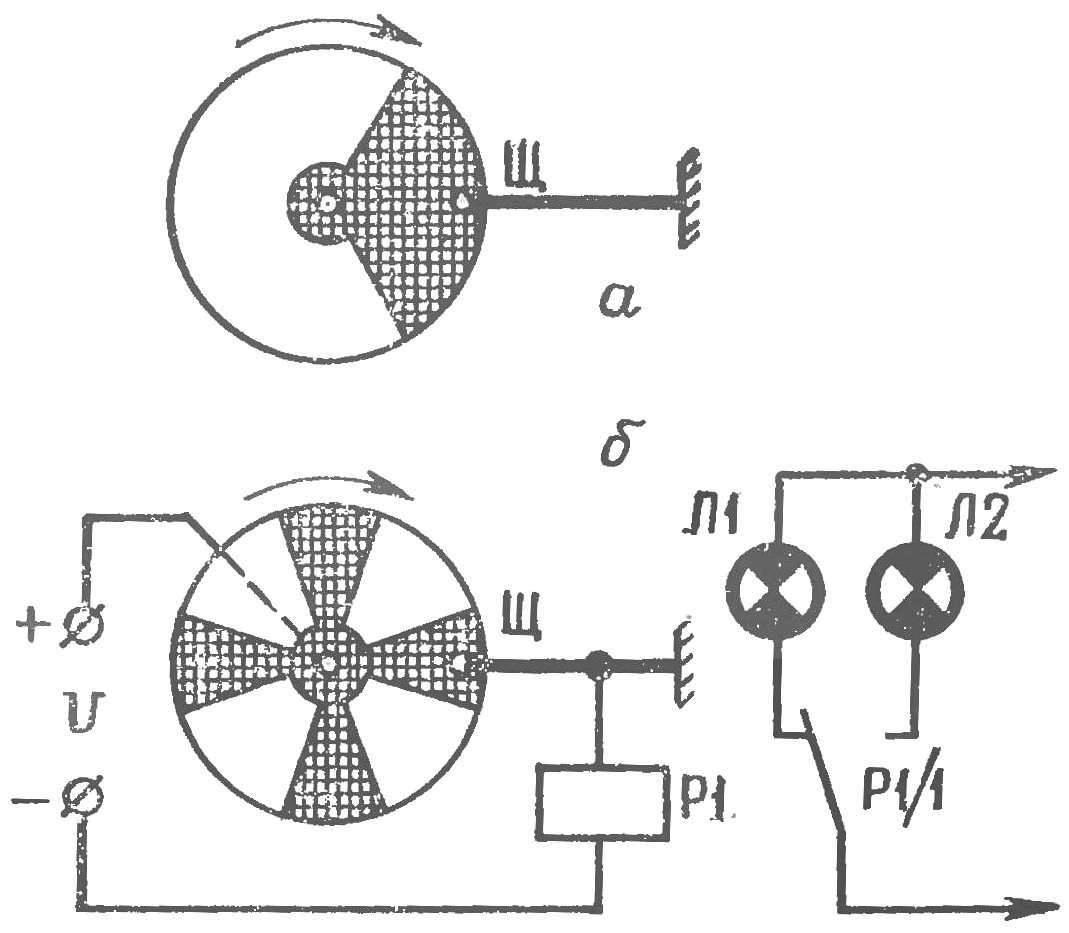
Fig. 3. Variator pure strategies.
At the top of the panel there is a red and green signal lamps. When the Select button is released, the machine itself includes one of them. The machine can include a signal light of the same color, and a burning lamp under the flap (in this case, the machine “tells the truth”), or red light when the flap light green light: the machine is “trying” to trick your opponent.
If the machine is turned on the green light, that is, it is admitted that under the flap the green lamp is on, then its opponent can only make one point, clicking “Believe.” Counter his points captures the win.
If the machine is turned on the red light, that is, claims that under the flap burns the same (and it could be otherwise), then the player B — two options. If he believes and press the “I Believe”, the counter machine will add to her one point. Not believing player B moves to the right the flap that says “do Not believe” to make sure which bulbs are included. If the machine didn’t cheat, he gets two points; if you tried to do — gives the same to the enemy. The party is over.
To begin the next, click on the “Reset” button. In this case, all mechanisms of the machine are reset, and the counters continue to sustain earlier points. In the beginning of the game the counters with the help of special levers are set to zero. The number of batches is unlimited. Tog wins from opponents who will score during the game a greater number of points.
Analyze the operation of the machine according to his concept (Fig. 4).
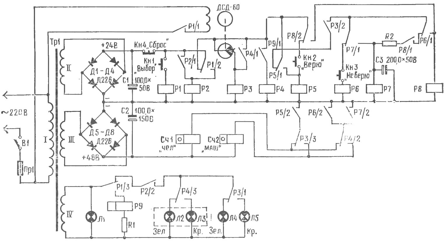
Fig. 4. Schematic diagram of the playing machine.
Before the game machine is connected to the power source; the lamp L1 as an indicator of the readiness of the machine. Then the person playing with it, clicks and 2-3 seconds releases the button KN1 Select. The voltage supplied to the relay coil R1, and it works. The contacts R1/1 are synchronous motor DSD-60, which begins to rotate the contact disk of choice to pure strategies. At the same time contacts R1/2, the voltage applied to the relay coil R2, and contacts R1/3 — to the winding of polarized relay P9. Relay P2 is triggered, and prevents its contacts R2/1. Simultaneously, the contacts R2/2 preparing for the inclusion of L2, L3 under the flap and signal lamps L4, L5.
The anchor relay P9 starts to vibrate with the frequency of the contacts P9/1 alternately closes the circuit and simultaneously de-energised relay coil R4. However, relay R4 fails, so as the contact PI/2 is switched off and the tension on the relay coil R4 is not received.
When the Kh1 button is released, relay R1 is de-energized: the contacts R R1/2, the voltage applied to the logical device of the machine, consisting of relays R3—R8. Contacts R1/1 switches off the motor DSD-60, and contact the drive stops. Thus, depending on the situation, which took the drive relay P3 is turned on and de-energized. The probability of both 1/3 and 2/3. Contact PI/3 disconnect the polarized relay R9 and the voltage applied to the L2—L5.
Contacts P9/1 be or closed or open depending on which of the end positions stops the anchor of a polarized relay. Both positions are equally probable.
Consider first the case when contacts P9/1 has been closed. Relay R4 is activated, its contacts R4/3 include red lamp L3 under control; contacts R4/2 are preparing the electrical circuit of the counter points to the machine Сч2; contacts R4/I include the winding of relay R3, and this relay is actuated regardless of the position of the contact disk. Contacts R3/1 include a red warning lamp L5: the machine “says” that, under the flap is a red lamp L3. At the same time, contacts R3/2 preparing for the inclusion of a host logical unit that contains the relays R6—R8, and contact R3/3 — counter machine Сч2.
Return the player B or he believes the enemy machine or not. If you click Кн2 “Believe”, relay R5, contacts R5/1 is responsible for the self and however removed power from the node logic devices (relays R6—R8). Through contacts R5/2 the voltage supplied to the counter Сч2; it works and adds one point.
Not believing the machine, the player B pushes the valve. When this closed contacts Кн3 and relay R6. The contacts P6/I and P6/2 turn on the power to the relay R8 and the meter Сч2 (relay R4 is energized). The counter adds to my testimony one point, and relay R8 is self-locked, and P8/1 prepares the supply circuit of the relay R7.
Release the valve under the action of the spring returns to its original position: contacts open Кн3. Relay R6 is de-energized, and its contacts R6/1 switch P7. After 1-2 s (the delay is determined by the time constant circuit R2, C3), the voltage at the capacitor C3 becomes sufficient for switching the relay R7. It cambiocorsa and includes contacts P7/2 Сч2 counter that counts down the second point.
Now consider the second case: contacts P9/1 open, relay R4 is de-energized, and under the flap off the green lamp L2. In this case, the relay R3 is determined by the position of the contact disk. When relay R3 its contacts R3/1 include a red warning lamp L5 (the car “tries” to deceive the enemy). If relay R3 is de-energized, the green signal light L4 (the machine “recognizes” that under the flap of the lit lamp of the same color). In this case, the enemy does not remain anything else as soon as you click Кн2 “Believe” is triggered its counter Сч1, adding one point.
When lit red signal lamp L5, the person again has two options. If he believes and clicks Кн2 will counter points to the machine, adding one point (contact R3/3 is in the right position according to the diagram). If you do not believe and will pull back the flap, then two points adds counter Сч1 (contacts R4/2 are in the left position according to the diagram).
The party is over. Clicking Кн4 Reset, remove power from all relays on the schema. The logical unit of the machine returns to its original state. You can start the next batch.
In the scheme of the machine used electromagnetic relays tap changer, the polarized relay RP-5, pulse counters of the type SEI-1, lamp L1 —L5 type LN 3.5 V, the capacitors C1 — C3 — electrolytic К56-3, resistors R1 and R2 are selected when adjusting the machine. The DSD engine-60 — synchronous, designed for an alternating voltage of 220 V; its shaft is 60 R/min. Button KN1, Кн2, Кн4 — bell. As Кн3 used contacts from the relay. Power circuit breaker — single pole toggle switch.
The power unit of the machine consists of Tp1 transformer and two rectifiers. The first rectifier bridged by diodes D1— D4, provides a voltage of 24 V to power the relay P1—P8. The second, also assembled bridged by diodes D5–D8, gives a voltage of 48 V to power meters Сч1 and Сч2.
Transformer Tp1 is wound on the core Network Ш20Х20 mm. 2750 winding comprises turns of wire of PEL 0,15; winding II — 300 turns of PEL of 0.3-5; winding III — 600 turns of PEL 0,15; winding IV — 44 turns of PEL of 0.5.
All parts and components of the machine are mounted on horizontal metal chassis (Fig. 5).
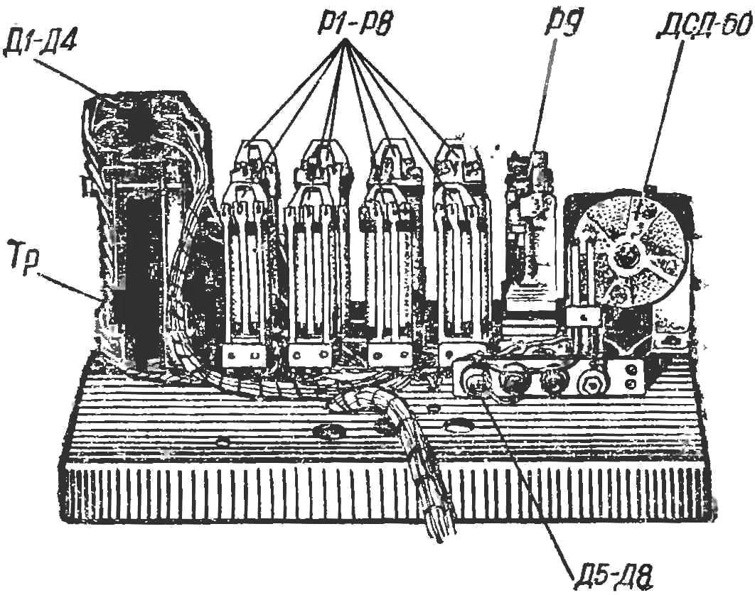
Fig. 5. Location of parts on chassis.
Machine for the game “Believe it or not” was built by students of the physical faculty of the Sverdlovsk state pedagogical Institute. To test “game-ability” of the machine, the students installed it in one of the Dorm rooms and offered to fight him for everyone (previously it was fixed the levers reset the counters, so they cannot be returned on the wheel). Within a few days the students played with the machine was held more than 2,000 parties — And by the end of this kind of competition the score was in favor of the machine.
D. can be visited, candidate of pedagogical Sciences, Sverdlovsk, Russia
Recommend to read
 WITH A SOLDERING IRON FISHING
Of course, not new, but are already served, in particular, the type of APCN-40: it has an elegant plastic handle and a tubular body which is very suitable for making winter fishing. In... THE MIG-9
Scale model: 1:33. At the end of the second world war, the Soviet Union intensified work on the creation of jet aircraft. Four OKB (Mikoyan. Yakovlev. Lavochkin and Dry) began...
