
 Wireless microphones VHF with frequency modulation (FM) is very convenient when you need to organize one-way communication over a short distance. For example, between residential and utility rooms, parents and children in the yard, and between the crews of the vehicles, the business partners in the market, aid in the organization of cultural activities etc. is Indispensable these compact electronic device when capturing and listening to sounds in nature, as between the information source and the recipient occurs distance, largely conditioned by the “range” used VHF radio.
From the existing analogue developed by me improvised RM is characterized by a simple structure, good frequency stability, a small number of parts and its compactness with a substantial increase in the communication range. Moreover, with the use of unpackaged parts and thin disk batteries with a diameter of 25 mm Panasonic the size of the device can be reduced almost three times. True, and time will then be reduced to two hours.
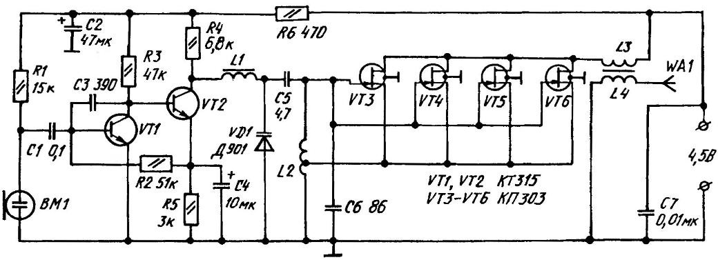
Schematic diagram of the proposed device is designed so that the simplicity of the setup, you can obtain a wide output power range by increasing the supply voltage (3 to 4.5) and the number of field-effect transistors (2 to 5 units) in the master oscillator. Then the range of the broadcasting line-of-sight increases from 40 to 200 meters. The wireless microphone has high sensitivity at low frequency and catching, for example, the ticking of the alarm clock at a distance of six meters. Properly collected scheme operates and when the voltage drops to 2.5 V, the calling, by the way, a small reduction in the frequency of the transmitter.
High sensitivity of the device to provide sound electret microphone and amplifier low frequency (ULF), executed on transistors VT1, VT2 and current consumption is not more than 1 mA. The capacitor C3 is slightly higher cut frequencies for more natural tone of the sound. Chain R6C2 prevents instability VT1 and VT2 by reducing the supply voltage. Resistor R2 sets the gain of the ULF.
Working with the nominal value of R2, which is indicated in the diagram, ULF has such a high sensitivity that if the average volume level of the sound source located, for example, at a distance of 2 m from the microphone, the RM might even “choke”. So if you plan to use this device for eavesdropping at a distance of 0.3 m from the object with the subsequent reproduction quality UHF receiver, the resistance of the resistor R2 should be reduced to 15 kW.
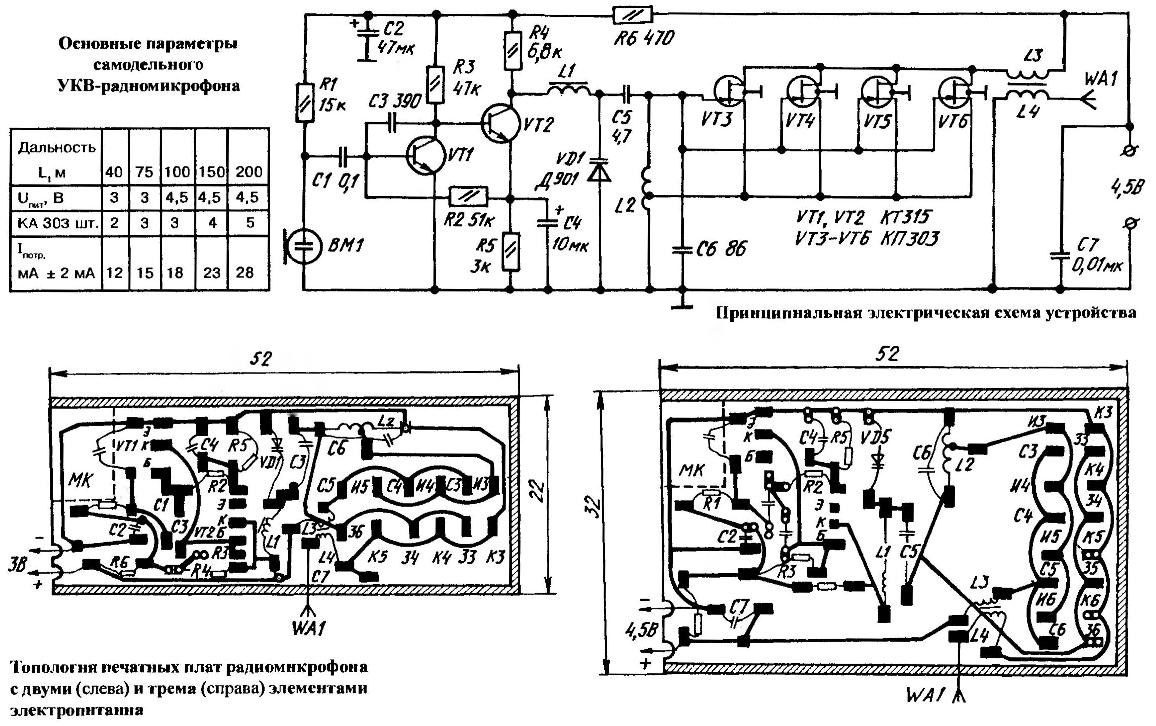
Perceived electret microphone and amplified ULF signal comes through the choke L1 on VHF FM generator (VT3-VT6, L2, C6, C5, VD1), whose power (and, hence, the “range” of the RM and supply current to the device) depends on the number of parallel-connected field-effect transistors (see table). And thanks to the coils L3 and L4, wound on a ferrite core, high frequency power is supplied to the antenna, followed by radiation transmission from the RM in the air.
The device used available resistors MLT-0,125. Capacitors are also not scarce: C2, C4 —any electrolytic, C6, C5 — tubular or disk with a small HEEL, the rest of any design. Microphone electret, dvuhmestnoe, with a diameter of 10 mm and a thickness of 7 mm, the body is connected with “ground”. Such import of used portable stereos inexpensive models.
Not from the category of scarce and semiconductor devices. In addition, almost all they make a replacement for the standard analogues. In particular, it is specified in the scheme of semiconductor triode KT315 you can use КТ3102. As VT3 —VT6 acceptable field-effect transistors КП303—КП302, preferably with the same or similar value electrical parameters. The varicap VD1 you can apply any. It is possible here… even a Zener diode in glass enclosure having a voltage stabilization more than 5 V.
Now, about the choke and inductors. Inductor L1 is wound on the ferrite with a diameter of 2,8×12 mm wire type ПЭВ1 with a diameter of 0.1 mm to fill the core. Well, for L2—L4 applied ПЭВ1-0.6. And L2 has 10 turns wound on a rod inscribed with a ballpoint pen, with a tap on the 4th, considering (see schematic diagram) from the grounded end. The core of L3, L4 — one, the ferrite. Its diameter is 2.8 mm, length 12 mm., the Coil L3 contains only 4, and L4 — 3 turns.
The antenna is 800 mm pigtail ПЭВ1 -1 wound in a spiral with a pitch of 1 mm on the disc with a diameter of 12 mm. Soldered the antenna to the intended pad on the PCB of one-sided foil of 1.5-mm fiberglass or Micarta.
Power supply RM serve (depending on the embodiment), two or three galvanic cell type “AAA” from remotes, which generally lasts 12 to 20 hours of continuous operation. They are located under the circuit Board in the basement of the building. For compactness RM that the power switch is in the both variants of the design missing. But if desired, it can be easily installed. However, this will entail an increase in the size of the device.
In any case, the housing preferably homemade. The side walls preferably run from impact-resistant colored polystyrene thickness of 3 mm. should be cut the grooves for the printed circuit Board and the lid of the battery compartment. The front panel and cover on the battery compartment — fiberglass 1.5 mm thick. the Contacts for the power supply can serve as pieces of foil glued to the rubber clamps with dimensions of 10x10x1. 5 mm.
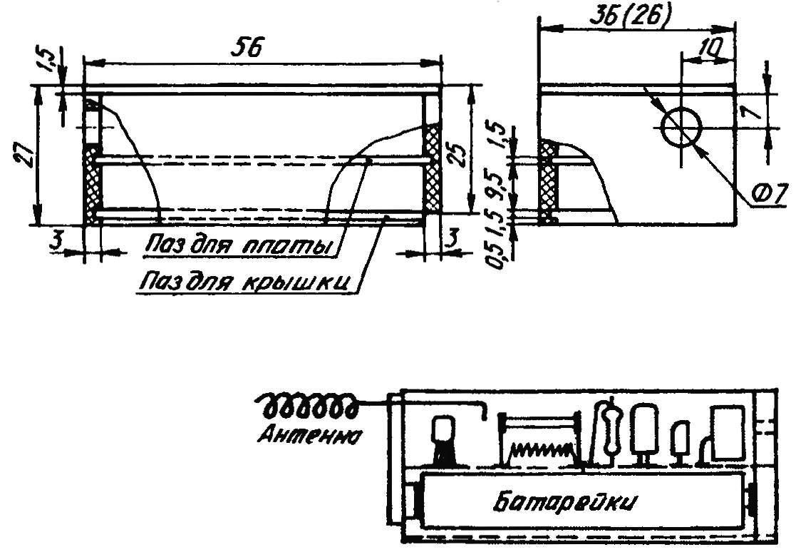
The case and the layout of the wireless microphone
Device setup is extremely simple. Even not too experienced in electroradiotechnics beginners execute it quickly.
Temporarily setting instead of the capacitor C6 “shells” of a capacity exceeding 250 pF is fed to the transmitter voltage. The measure supply current to the device, which should be within the limits specified in the table for the selected range.
Setting used in conjunction with a wireless microphone receiver VHF frequency-free radio stations and television channels, slowly rotate the rotor of the variable capacitor, soldered in RM instead of SB. Podlodowski under the radio, determine the value of “shells” — preferably on the testimony of a special capacitance meter. But you can navigate and sector ceiling of the temporary plates of the capacitor.
“Shells” may be given and return S6 (refined capacity!) in place. It is desirable that the value selected capacitor of several picofarads exceeded the capacity have been in the tuning operation of the “shells”. This margin is necessary for accurate adjustment of the radiation of the RM, which is produced by stretching of the turns of the coil L2.
And again. When adjusting the generator set up RM so that the radio took to be the fundamental frequency of its radiation in the so-called “DSLR”, because at a close location of these devices the signal is strong enough for the occurrence of such confusion.
You can understand the quality of reception of both radiations. Excessively noisy signal is an ill-fated “SLR”. And need a clean signal.
When you are finished configuring the device, it is useful to see on the TV there is no interference from RM on those TV channels which are broadcasting. If it turns out that there is interference, it is necessary to adjust the carrier frequency of the wireless microphone, for example, by squeezing or stretching the turns of the coil L2.
D. ATAEV, Sterlitamak, Bashkortostan
Recommend to read
 GLUE WILL NOT DRY UP
How carefully any work with glue in a tube, still the hole is clogged by dried particles. And even cover somewhere of the sunset, you will not find. Simple device eliminates these... “MAGIC” LANTERN
Good help the Modeler will have an overhead projector, which is easy to make yourself. It can be used to increase or decrease to the appropriate size drawings, projecting them on the...
