 Appeared in stores digital multimeters seriously pressed the usual “switches-instrument Toolkit”. However, expensive components (the battery), and sudden circuit failures limit the possibility of using these multitesters. And in the field-conditions, they are generally unsuitable, as ranked by now outdated “respectable” turnout isometry: danger drop, break, drop solder, the difficulty in retaining “the weight” during the measurements all lead to the loss of an expensive device. Therefore it is better to make a special microtester that meets the stringent requirements of the work in “field” conditions and convenient as a wrist watch. Well base and a “measurement head” of a homemade can, in particular, become familiar to all and accessible indicator of the recording level, is widely used at the time in designs of transistor tape recorders domestic production.
As they say, an evening at the Assembly — and in the hands of homebrew is quite compact, user-friendly device (see Fig.), able to measure and monitor the most important parameters of electrical circuits, as well as the efficiency of equipment in General. It is essentially a voltmeter with a measurement range 5 ohms, 5, 50 and 500 In both permanent and alternating current.
It is useful, apparently, to emphasize that the 5-volt scale is convenient to use when measuring the voltage of galvanic cells and batteries, as well as Uout devices are charging them; ten times more — indispensable during work on side chains of transport equipment; 500-volt — is applied to check If I IP industrial network, the anode voltage in tube equipment.
Of course, all limits can be changed by appropriate selection of resistor R1. From the current measurement has a meaning beyond the little used method. But if necessary you can provide that would inevitably lead to an increase in the size of the device. Contact Jack with adjustable measurement range are displayed on a small DIP connector (pitch 2.5 mm).
Coil head-an indicator on the tape is, indeed, highly sensitive, therefore, to obtain relatively stretched scale it must be bridged by the aforementioned resistor R1 (suggested value of 16 Ohms). Theoretically, this should increase the battery discharges during the measurements, although in practice it is able to maintain its performance to natural self-discharge.
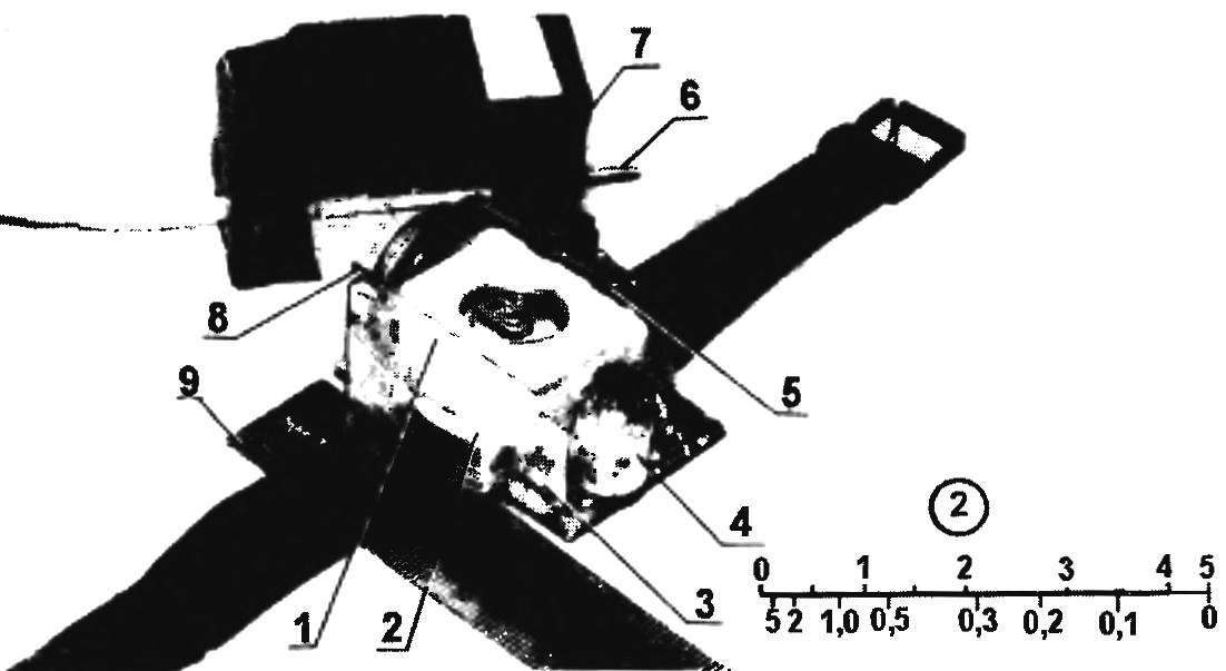
A circuit diagram of a wrist of the tester, and its embodiment in reality (disciplic line is depicted next to a visual scale):
1 — dial indicator (cassette recorder); 2— paste the paper dial; a 3 — angled bracket (2 PCs); 4 — controller characteristics; 5 — jacks for different ranges (socket small DIP connector); 6— measuring “end” (stranded microwire with a homemade mini-probes on the ends, 2 sets.); 7 — case (cardboard covered with epoxy followed by curing in the oven); 8 — disc battery (D-0.1 a homemade pin socket); 9— plastic strap (wrist watches)
Almost all electrical schematic of the device (simple, but reliable) can be easily mounted on a mini Board of one-sided glass epoxy (to split, if one — sided). Is used and plastic watchband. For its mounting to the PCB soldered segments 2-mm wire. Other details of the installation (including bracket for mounting a measurement head and a contact socket of a power source, which is battery D-0.1 or more small-size electroplating the disc element from the electronic clock) is also tightly soldered to the Board.
The probes are made of flexible wires handset. Measuring tips — it cuts steel wire (spokes), 2 mm thick, inserted in place of graphite in knots pencils with interchangeable heads and secure to the desired length of PVC pipe.
Scan the body of the instrument should be carefully calculated and drawn on graph paper. Then it should be cut from thin cardboard, glue, silica glue, and after coating a liquid epoxy diluted in acetone, is dried in an oven. Will box, not inferior in strength even to the PCB. Well, if the silicate bonding will still eventually crumble, we have to consolidate this case with an additional layer of any nitraria (for example, “Moment-2”) and restore the elegant appearance of the product by painting it with enamel or nitrocellulose lacquer in the desired color.
In conclusion, two practical advice. If the fasteners of the housing on the circuit Board of the device has no space left, it can be mounted in the side walls of transparent sticky tape (duct tape) through the bottom of the base unit. Don’t be upset if the installation of microtester at hand you don’t have the required small-sized variable resistor R8 nominal value of 220 Ohms; because it can be replaced by any other suitable envelope, designed for resistance to 1.5 ohms (with the obligatory papaikou 220-lot of shunt).
Vladimir SILCHENKO, S. Vikulovo, Tyumen oblast
Recommend to read
 THE MYSTERIOUS “HISPANO-SUIZA”
Luxury car with four-seater body "convertible" — a Museum piece. Through the entire radiator inscription: "Hispano-Suiza". In the top tank of the radiator you can see another emblem. It... HOW TO MAKE “ZIMMERIT”
Anyone interested in the history of armored vehicles is well known that highly characteristic feature of the external appearance of the German tanks since 1943 was an anti-magnetic...


