Intermediate gearbox is located under the engine hood and is attached to the cool side member of the frame. To stop gear will not, because it is in detail reflected in the figures.
In the steering drive mini-tractor used units and parts from different techniques. For example, the steering mechanism is taken from GAZ-53, angular gear, from tractors K-700, CV-joints — steering wheel drive tractor MTZ-80; from the same tractor and some tie rod end (the rest of the car ZAZ 966).
The front axle is a so-called floating type completely homemade. It is made mostly of thick-walled pipes and is suspended from the frame by a solid hinge (in fact a sliding bearing with bronze bearings), the supports of which are attached to the bumper beam and the corresponding frame. Powerful beams give the bridge the required strength and rigidity, because what whatever the period is missing on the tractor and the load from shaking on the uneven ground front axle feels decent. Brackets screwed axle steering knuckles with king pins and wheel hubs from the car ZAZ-966. From “Zaporozhets” and the front wheels.
Rear axle mini tractors from GAZ-51, cropped to gauge the size of 1200 mm. it is attached To the frame with two ladders. Immediately say that the process of extrusion and cutting is “stocking” and the back of the semi-axes
bridge is the most difficult in making my mini-tractor. At least it was for me, so as to perform these activities had in terms of state farm’s workshop, where there was a powerful hydraulic press and lathe. On the machine I bored through and drives the drive wheels (they’re from the tractor MTZ-80) to the landing sizes of the hubs of the rear axle. Themselves wheel from the front of the tractor T-40. His twenty tyres with the “tree” provide good traction and flotation of a homemade machine.
Brake — hydraulic, with drive only to the front wheels. All components and parts brake, of course, from “zaporozhtsa”. In the long term — equipment tractors separate brakes and wheels.
diagram of the steering drive:
1 — steering wheel; 2 steering column; 3,5,7 — universal joints (steering gear of the tractor MTZ-80); 4 — driveline; 6 — angled gear reducer (I = 1, from tractors K-700); 8 — steering gear (GAZ-53); 9 — fry; 10,12,13 — tie rod end (MTZ-80 and ZAZ-966); 11 — short tie rod; 14 — long tie rod; 15 — the front wheel circuit
Front suspension:
1 — back support of a bridge hinge; 2 — the front axle: 3 — the front wheel hub with swivel knuckle (from the ZAZ-966) and a mounting bracket to front axle; 4 — front support of the bridge hinge
Front axle:
1 — strip (steel sheet s10); 2 — axis hinge bridge; 3,7— gusset plate (steel, sheet, s10); 4 — upper beam (pipe 60×8); 5 — lower beam (pipe 40×5); 6 — (pipe 57×5); 8 — bracket steering knuckle wheel
wall movement:
1 — manual chain hoist capacity up to 500 kg; 2 — the spring tension of the rope; 3 — wire (d4); 4 — the blocks in the direction of the tether; 5 — the elevating shaft; 6 — brace; 7 — Central thrust (tractor MTZ-80, short); 8 — longitudinal traction
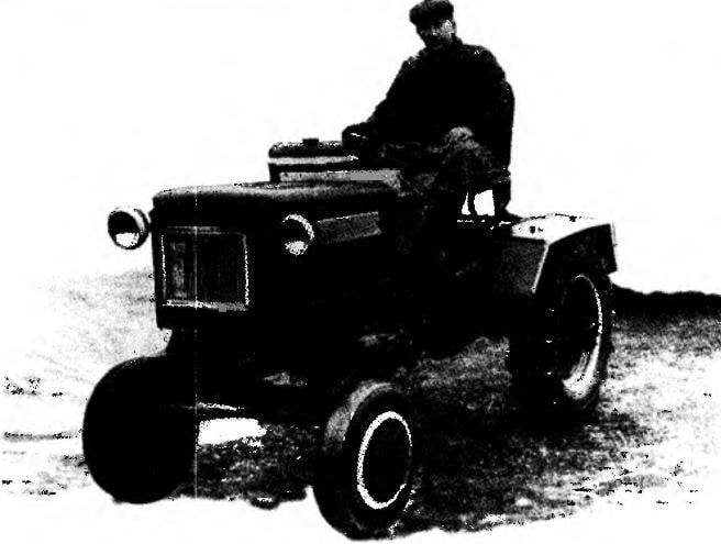
Appearance mini-tractors to determine forward facing, hood and rear fenders of the wheels. The lining and hood are made of body and doors of the old fridge. The hood leans to starboard. Wings are welded from sheet steel 3 mm thick. Lights, control libary and other electrical equipment are assembled, as it were, the forest of pine, from various machines and mechanisms (lights from MTZ-80 generator from the “Moskvich-412”, tumblers and wire from ZAZ-962, battery — 6CT-50).
The hinged mechanism made according to the known three-point scheme. Longitudinal and Central adjustable traction to form a simple and user-friendly design, with which the mini-tractor can agregate-ment with different working tools. The control rod attached to the frame at its lower rear part, and the Central rod to the upper cross-member between the vertical legs of the frame (not shown in the diagram). The lift linkage is driven, the basis of which is a hand-operated hoist mounted on the right wing and developing a force of up to 500 kg. Rope pulley blocks through the blocks, lifting the shaft and struts raises the control rod. In the work “floating” position of the guns up the slack of the cable selects the tension spring. This system works quite well, but the hydraulic drive, of course, much easier to operate and, over time, the manual lift mechanism hydraulic mounting will be replaced. Also plan to replace the engine for a more powerful and user-friendly — car “Zaporozhets”. So to develop a homemade car can be a long time — throughout the lifetime of the battery.
G. LEGOSTAEV
Recommend to read
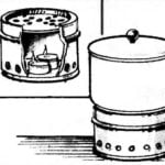 CANDLE IS NOT WORSE THAN THE STOVE
Whether from the Christmas holidays, whether family celebrations are often ogrocki candles. They can be used as a kind of steam tables — devices for maintaining food in a heated...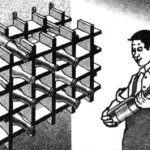 SHELF FOR… BOTTLES
This wall-mounted cellular shelving unit is very convenient for storing a supply of various drinks in bottles — from mineral water and wine to yogurts. They are visible, easily accessible,...
 Log “modelist-Konstruktor” reading since 1982. Since I am an active supporter of technical creativity. Farmersto now, but before when I worked in the local newspaper, tried to the extent possible, to popularise technical creativity among the readers. First released the category “DIY” and then a thematic band “the masters Club”. I have been publishing for Amateur construction, and in other publications — in the Republican youth newspaper “Leninets” in the Moscow newspaper “Gardeners”, in the newspaper “Victory”, in the journal “Farmer”.