ARMORED CRUISER 1ST RANK OF BAYAN

ARMORED CRUISER 1ST RANK BAYAN
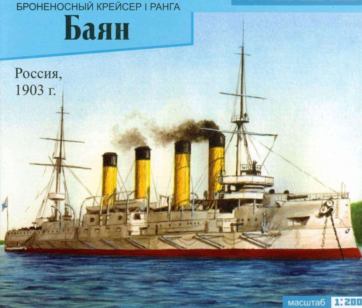
ARMORED CRUISER 1ST RANK OF BAYAN . Scale model 1:200.

Among the ships – participants of the Russian-Japanese war – “Bayan” is considered to be the best representative class cruisers of the Russian Navy. Work in the shipyard of La Seine near Toulon began in late 1898. December 21, 1898, the Emperor Nicholas II granted the construction of the cruiser name “Bayan”. The official laying took place on 26 June 1899, simultaneously with the battleships “Tsesarevich”. By this time on the stocks was already collected and the bottom of the cruiser, fitted the frames above the armored deck. The launching took place on 30 may 1900.

March 30, 1902 the Commission, chaired by captain 1st rank Grigorovich beginning of the acceptance of the cruiser.


3 APR command cruiser took the captain 1st rank Robert N. Viren.


April 24 on the “Bayan” profit, 370-person team and four officers. The French authorities reacted with great attention to the organization of moving of the crew from Dunkerque to Toulon, with separate train with a special accompanying. Along the route residents welcomed the Russian sailors, the stations were arranged demonstrations. In Lyon on the platform was built a guard of honor orchestra.


8 may “Accordion” out to sea on a factory trial, but was forced to return due to failure of steering gear. Adoptive trials was delayed until the end of the year due to the fine-tuning of boilers.


December 16, 1902 was signed the final reception act, which stated that “the cruiser has fulfilled all the conditions of acceptance tests and any penalties not be”.


January 1, 1903, standing on the Toulon RAID “Bayan” was raised St. Andrew military flag, Jack, pennant and joined the campaign. On 23 February, the commander of the cruiser received a telegram with orders to immediately follow at Brindisi for the Grand Duke Boris Vladimirovich and the Greek Prince Andrey Georgievich and to bring them to the Piraeus. The Grand Duke is located on Board the cruiser in the Admiral’s premises, the day was visiting Athens. In March, the eminent passengers arrived on the “Bayan” in Naples. Then, together with the battleship “Emperor Nicholas I” and gunboats “Brave” “Bayan” made the transition in Algeria, and took part in the celebrations in honor of the President of France.


On 6 June, the cruiser arrived in Kronstadt.


On 19 July, captain 1st rank Viren received secret orders of the chief of GMS rear-Admiral Z. P. Rozhdestvensky “urgently” after the Emperor review to explore the Mediterranean sea and from there the detachment of rear Admiral A. A. Virenius along with squadron battleships “Tsesarevich”, “Oslyabya”, “Emperor Nicholas I” to follow in Port Arthur to reinforce the squadron of the Pacific fleet.


25 Jul 1903 “Oslabya” and “Bayan” came from Kronstadt? but later their ways diverged. “Bayan” was ordered to go to France, and the “Oslabya” in England. In Cherbourg Viren received a telegram Rozhdestvensky, with orders to go further, without waiting for an Armadillo.


In the Greek port of Poros from the Bayan met with battleship “Tsarevich”, and on 25 September they went together to the Port said.


19 Nov 1903 the ships arrived to Port Arthur.


In the night from 26 to 27 January 1904 squadron was attacked by Japanese destroyers.


On the morning of 27 January, the “Accordion” took his first fight, coming close with the enemy until 19 KBT.


During the battle with the Japanese battleships and armored cruisers “Bayan” received ten hits of shells (caliber 152 mm and above) and 350 splinters. Holes ranging from 1.3 to 1.5 m did not affect its combat effectiveness.

On 14 July with the return on internal RAID, the Bayan struck a mine. The explosion occurred on the starboard side. Repairs took about two months (from 23 July to 15 September) and was carried out first in dry dock, and then afloat.


On 19 September the Japanese began shelling the internal RAID of the port and city of the powerful howitzers. September 27 “Bayan”, standing under the Golden mountain in the Eastern basin, includes four 280-mm shells. One of them struck the upper deck opposite the entrance to the car left on 17-m the aft bulkhead, causing significant damage. 11 Oct one of the two caught in cruiser armor-piercing 120mm projectiles struck the upper and battery decks and exploded in a residential deck.


Only from 27 September to 18 October, the cruiser was hit six 280-mm shells and ten medium caliber. Despite the difficult conditions, damage were corrected, the ship was maintained in an efficient state, and could go to sea.


November 22, the Japanese captured the most important position of defense — a High mountain and had already corrected it with your shooting. Began the destruction of our ships in the West basin. On this day, the sinking of the battleship “Poltava”, the 23rd — Retvizan, 24th — “Peresvet”, “Pobeda”, the cruiser “Pallada”.


November 25, the Japanese suffered a fire in the Eastern basin of standing at the wall under the Golden mountain “the Bayan”. Had to unload the ammunition and food. The morning of the 25th to the beginning of the bombing on the ship there are only a few specialists, the whole team was kept on shore in a safe place. The shooting of the cruiser began in the morning and lasted up to 17 hours. During this time, it was released about 320 280-mm and 152-mm shells. In the “Bayan” were about ten. In the residential deck, dangerously close to the cellar, broke out several fires. Had to flood both the 203-mm and all nasal cellar, the cruiser received a different nose and sat down on the ground. Shot holes were not, but because of increased precipitation, the water began to flow through the holes in the freeboard. Many shells exploded on the bonds, to cover the side of the cruiser. With the onset of darkness again unloaded a 152-mm projectiles and charges, and by morning, all suitable for firing ammunition were sent ashore.


November 26, the Japanese continued the execution of “Accordion”. With the beginning of the bombing had to stop all auxiliary machinery, the team went ashore. Up to 11 hours in the cruiser got about a dozen of the 280-mm shells, it lurched to the left side to 15th and sat down on the ground. All the rooms of the residential decks were flooded.


ARMORED CRUISER 1ST RANK BAYAN


After the occupation of Port Arthur, the Japanese picked “Bayan”. In 1906-1908, the cruiser made the refurbishment in Maizuru and with new boilers and guns Miyabara Vickers (2 203 mm; 8 152-mm, 16 76-mm) under the title “ASO” became part of the Japanese fleet.


In 1913, dismantled 8-inch tower, and in their place installed one deck 6-inch gun shield, and the aft gun raised on a specially erected for this add-on. Representing, apparently has significant military value, the vessel was sold to Russia in 1916, as happened with the former cruiser “Varyag” and the battleship “Poltava” and “Peresvet”.


In 1920 the old “Accordion” was rebuilt in Yokosuka in the minelayer capable of carrying up to 420 min were Excluded from the Navy list on 1 April 1930 and renamed “Hai Kan No. 4” (“excluded vessel No. 4”). Sunk April 8, 1932 during practical shooting by gunfire the heavy cruiser “Myoko”.


Specifications


Length between perpendiculars:…………………………………135 m

Maximum width at the midsection:…………………………………17.40 m

Average deepening:…………………………………………………..6.70 m

Displacement:………………………………………………………..7800 t

Artillery:……………………………………………………………….2 – 203 mm; 8-152-mm, 20 – 75 mm, 8 – 47 mm, 2 37 mm

Booking:

belt VL…………………………………………………………………..200-100 mm,

the upper belt and casemate…………………………………………………80 mm,

deck – 50 mm, barbettes……………………………………………….170 mm,

tower………………………………………………………………………..150/30 mm,

cutting………………………………………………………………………….160 mm

Capacity mechanisms:………………………………………………..16 500 l .with.

Speed:…………………………………………………………………….20,9 uz.


Assembly instructions bronchoscope cruiser I rank “Bayan”


The basic concept of this model is the possibility of making the maximum number of elements only of paper. The only exception is the rigging and railing are made from thread.


Some sketchy small parts (davits, gun barrel, mast) kompensiruet a sense of unity of the material and careful manufacture of these elements of the model from a distance от40-50 cm look more realistic than wire and wood.


The Modeler, working with paper, it is advisable to understand that this material not only speeds up the process of creating the model and reduces its complexity compared to traditional materials. The material is valuable. The viewer looking at the finished model, mentally or aloud says: “that’s it… out of paper?!” The inclusion of metal and wooden parts immediately turns the paper into a cheap substitute.


For this reason, it is not recommended to rely on the disguise of Assembly defects color, especially the underwater part of the ship. The feel of paper” not only forgiving, but making a kind of dignity some granteth the surface will disappear after the first layer of paint, but to get a really smooth surface is possible only as a result of multiple putties and polishes.


The only exception is the desirability, and even the need to touch-up the ends of the cut out parts with a color of their main surface. It is best suited for this purpose markers.


The model can be done with underwater part and the waterline. Both options have their advantages. The implementation of the underwater part requires special care and technical skills, but if any here can show you the possibilities of paper as material modeling.


The performance of the model without the underwater part at the waterline, greatly facilitates the Assembly process. In addition, the ship appears to us. as we could see it in reality.


Legend:


Part numbers are always in rectangular frame. Room no frame marks the spot, which is glued to the item delivered to the room. In the parts kit, splice, with the help of slots, marking the inserted part near the slot.


The letters “R”and “L” complementary numerical designation, refer to the membership details accordingly to the right (R) or left side (L). Such items always have a pair.


The letter “W” indicates a section that should be cut from the part without disturbing its external contour. As a rule, it is easier to do in the first place, before the separation of the part from the sheet.


Any bend parts are preferably pre-incision. Where this must be done with high precision, the set of dash-selectedonly 1 mm. mandatory such notches, as well as stroke the rear side supplied with double-sided detail.


Stage 1 Assembly


Straightening the paper clip to disassemble the booklet on the leaves. Divide the leaves on the bending place.


Sheets with numbers 1,3,4,6, top l ist 2, and in the case of a mod eating and under water Noah part and l ist 5 glued to cardboard with a thickness of 1 mm.


In the case of use of water-based glue of the PVA should pay special attention to the prevention of deformation of sheets: the adhesive is applied only to the cardboard, glued a pair of cardboard-the paper is immediately sent to the press and kept there until complete disappearance of the feeling of dampness.


Of the items 001-004 glued the waterline. Bonding is performed back to back with the seam reinforcement strips of thin paper. The grey strip on the glue sets frames 005-014. Their slits are inserted fore and aft sections of the plane 015 and 016 and preceived to the waterline at the contact. This is followed by the frames 017 and 018 and the longitudinal connection 019*021. All the details should enter into each other with a very light force, the frames * to remain upright but the waterline is flat and tight to the surface, for example, of the table.


The numbering in the frames is glued to the top of the armor belt 022-031, battery deck 032-043 and the bow frame 044. Most of the details here pairs, bonding them to each other to form the ledge (and. if necessary, and drying under pressure) should be performed before mounting on the frames.


Main deck 046-049 glued butt joint with reinforcement paper strip from the bottom, and then after drying, the seams under pressure is attached to the ends of the frames and longitudinal ties.


Stage 2 build (to create the model without the underwater part skipped)


From the bottom to the waterline just below the surface are bonded underwater parts of frames. Black square dots on the aft frames are designed for modellers who disagree with the introductory part of this manual and decided to replace the propeller shafts are made of paper on wooden sticks or metal spokes. In this case, you should turn them into the holes of appropriate diameter before mounting on the waterline.

Immediately after installation, the frames should be assembled keel frame 063-067 {from the extremities to the midsection), longitudinal relations 06В-071, and 072 parts. In places of their contact with the waterline – stick.


Before complete drying, it is important to control the Assembly. The line of the keel should be perfectly straight frames perpendicular to the waterline.


Stage 3 build (to create the model without the underwater part skipped)


Cut out parts of the sheathing 101 -111 to finish Painting their edges with a red marker and give the necessary form. You can also paint the ends of the frames are acrylic or gouache paint. The cladding lead in numerical order from the midsection to the extremities.


Bilge keels have in cross section the shape of a triangle and glued to the hull without valves, ‘in the end”.


At this stage, it is also desirable to make the stand {detail 140-145).


4этап Assembly


At this stage it is more convenient to postpone the end of the casing and to mount the main volume on the main deck – parts 150-199 undesirable. The only potential problem at this stage – predefinie the crease in the scan logging. Carefully review the Assembly diagram!


5 the build stage


Plating freeboard 200-219 is in the order of numbering and can cause problems only in the aft in case of inaccurate execution frames.


Ends Assembly trim mounting armor belt 112-113, These details presented in two versions: wide – for the model with an underwater part (the bottom of the belt is glued on top of the skin), and narrow for the model without the underwater part. Installation procedure-from bow to stern.


6 the build step (when creating the model without the underwater part skipped)


The screws and the wheel that shut down underwater part requires the utmost care and thoroughness of execution. Parts 124 and 125 should have a cross-section of lenticular shape. The front and rear sides of the paddle blades can simply be glued together, and you can also give them volume, carved arched front side, gluing along the contour to a flat rear side and then cutting along the contour.


7 stage of Assembly


Chimneys are a combination of two cylinders, the alignment of which is achieved by inserts 376, glued to the inner cylinder (painted black inside). Logging first glued the outer cylinder, and inside it is inserted into already assembled combination of the other parts. 1-I pipe has the sides flat areas, which is achieved by gluing to the inner cylinder of cardboard plates 377 and gluing them to the outer cylinder.


Before mounting pipes on logging, it is desirable to pierce the holes for the stretch. The ends of all the black parts to handle the marker.


8 build stage


So, the cruiser has acquired the basic shape, stands firmly on a stand (or Desk) the next step will be to chalk the cue details the side, deck equipment, guns, mast, etc. to Regulate the order of their Assembly appears to us to be unnecessary. You should pay attention on some of the subtleties.


Relingowe the fence, sometimes there are small tarp, first cut, and then glued together. Its outer side is 0.5 mm more inside. This over the fence and is fixed on the base.


Torpedo net is made of pipes 259-260 g flattened at the ends to reduce the diameter.


Details of the mast – stingi, yardarms, gaff, rods (all except masts) have V-shaped cross-section and require touch-up the ends, back side and very careful bending.


9 the build stage


Manufacturer of boats starts with the installation of the strip 485 on the casing (image plating boat inside!). Bending the strip 485 in half, begin to glue it outside to Board the boat from bow to stern. When he reached the cut, bent the casing so that the slit disappeared, and continuing to stick the strip 485, fix this situation. The challenge is to repeat this procedure for the other side for the other boat, creating the same curvature.


ARMORED CRUISER 1ST RANK BAYAN


Further the process of assembling the boats in the diagram and the complexity is not


10 the build stage


Rigging is the last stage of the model. The stays and shrouds of each mast, it is better to pull simultaneously in order to prevent its distortion. All the threads which are attached to the pipes, it is advisable to start to mount it with mount to the tube.


Relingowe fence is created with the help of the conductor being assembled from parts 498 and 499. Post-tensioning strands are impregnated with a varnish or adhesive (e.g., liquid PVA), and after it dries cut and assembled on the foredeck, Utah and marsovia site.

We wish You a successful Assembly and enjoyment of the result.


The materials to build a model of the ARMORED CRUISER RANK 1 BAYAN (download)

Recommend to read

  • RIDING ON THE TRUCKRIDING ON THE TRUCK
    Even the ancients said that the child, playing, exploring the world. And with the advent of various kinds of mechanical toys, followed by electric and electronic (signs century...
  • SCREW TIGHTLYSCREW TIGHTLY
    In cases when you want to prevent turning of the screw, screwed into a Board or plywood, I use a very simple way. Of stiff wire or a nail, whose diameter corresponds to the width of the...