
 COASTAL DEFENSE BATTLESHIP “ADMIRAL USHAKOV”. Scale model 1:200.
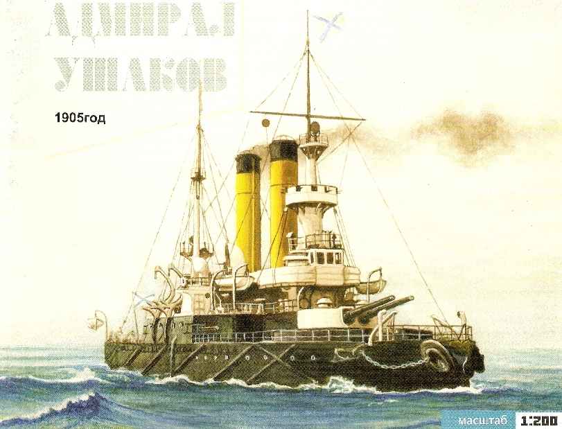
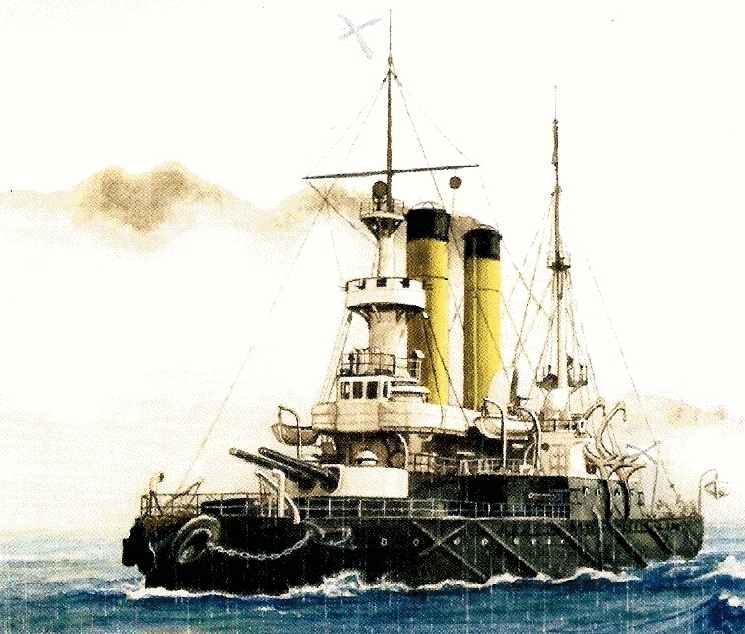
One of the most famous ships of the Russo-Japanese war, the battleship “Admiral Ushakov” was laid on 22 October 1892 at the shipyard Baltic shipyard in St. Petersburg in accordance with the shipbuilding program in 1881, launched in October 1893 and commissioned in 1896. In addition to “Ushakov”, was built two sister ships — “Admiral Senyavin” and “General Admira Apraksin”.
After commissioning, the battleship served in the Baltic fleet. Beginning in 1904 war with Japan demanded the urgent strengthening of the naval forces of Russia in the far East. Locked in Port Arthur, the 1st Pacific squadron at the outset of the war suffered heavy losses. The tsarist government adopted the decision to send to the place of fighting the 2nd squadron, the core of which were the newest battleships type Borodino, at first did not affect the fate of “Ushakov” and his fellows. Squadron commander Vice-Admiral 3. Rozhestvensky abandoned the outdated battleships. Only later, when the 2nd Pacific squadron was already in transit to the far East, under public pressure, the decision was made to improve. In formed for this purpose, a Separate detachment of ships besides the battleship “Emperor Nicholas I” and the cruiser “Vladimir Monomakh” was included and all three battleship of coastal defense.
Before going to all of the troop ships was hastily completed repairs and carried out a minor upgrade to a more serious change was not simple time. By early February 1905, the equipment of the detachment was completed, and soon the ships left Libau. On “Nicholas I” kept the flag of the commander of the squadron of rear-Admiral N. I. Rich. “Ushakov” was commanded by captain first rank Vladimir N. Miklukha, the brother of the famous traveler and ethnographer N. N. Maclay. On April 26, a solemn ceremony of the men have joined the squadron, and on 14 may in 14.08 shot from the flagship of the battleship “Prince Suvorov” started off so sad for Russia the battle of Tsushima.
 At the time of tie battlefield of the troop ships were the last in the Wake of the column, and active participation in the shooting could not accept. The Japanese, concentrating fire on the head “Suvorov” and the “Oslabya,” did not pay attention to the end of the column. Soon, however, the range of the guns of the detachment were the cruisers “Nisshin” and “Kasuga”, but having the advantage of speed and getting some damage, the Japanese soon came out of the fire. With the death of the “Oslabya” and failure of “Suvorov” ended the first phase of the day of battle, while opponents went, but around 15.40 battle again broke out all along the line. Gradually, the Japanese fire was concentrated on the remaining Russian battleships, and soon the ships of the detachment was in the center of the battle. “Ushakov” at the time covered the case has been damaged the battleship “Navarino” by calling themselves the hail of enemy shells. The first hit the starboard side near the waterline, but the most dangerous was getting another shell in the bow, which caused flooding of the entire nasal branches up to 10 frames. The Armadillo sat down his nose, lost up to 4 knots speed and to obey the helm.
In the last phase of the daily battle of the troop ships fired on the armored cruisers of Vice-Admiral X. Kamimura. In the dusk have lost their strongest ships of the Russian squadron continued to move to Vladivostok. Around 23.00 corrupted “Admiral Ushakov” has lagged behind the rest of the ships, and the next day after 15.00 the lone battleship was discovered armored cruisers “Iwate” and “Yakumo”. The Japanese, inspired by the surrender of the remnants of the squadron that raised the signal: “Advise you to give up. Your flagship surrendered”. After reading half the signal, VN. Mikluha said: “Continue, we need to know. Down the answer, open fire!”. At first, the Japanese cruisers were slow in returning fire, apparently hoping to “Ushakov” as a trophy and hope that his shooting will stop. But when the Russian shells began to go off the boards, the Japanese withdrew to a safe distance and opened fire. The range of their guns was higher than on the “Ushakov”, so all combat impunity they actually shot the Armadillo, holding at a distance, inaccessible to his guns.
After a few shots stopped, the tip of the bow tower “Ushakov”. It began to rotate manually, but the resulting roll had to make it quite difficult. After 20 minutes it was broken right nasal 120-mm gun, the battery started the fire, even after 10 minutes 203-mm projectile made of a large hole at the waterline under the bow tower. On the bridge and upper deck by this time it was all swept away by a hail of shrapnel. The roll to starboard had increased so much that made it impossible to fire from towers. Making sure that the combat capabilities of the ship are exhausted, the commander was ordered to sink a battleship. On the ship and opened the seacocks, the team were ordered to jump overboard. In a few minutes after that, “Admiral Ushakov” lay on the starboard, capsized keel up, and then down the stern disappeared under the water. The fate of the ship has divided its commander, the senior officer and over 60 team members.
After passing the remnants of the squadron’s two remaining battleship “Admiral Senyavin” and “General-Admiral Apraksin” became part of the Japanese fleet under the names “Mishima” and “Okinoshima”, in which he served for more than 20 years. “Okinoshima” was scrapped.only in 1939, and “Mishima” was used as a floating target and was sunk on maneuvers in 1936.
Tactical and technical characteristics of the battleship “Admiral Ushakov”:
Displacement, t — 4125 (4648 in fact)
Length the greatest, m. — 86.4
Reservations mm — belt in VL 152-254; tower 203; deck 38-63; fighting cabin 203
Weapons — 4-254 mm; 4-120 mm; 2-64.5 landing guns Baranowski; 4 submarine 381 mm
THE
Speed, knots — 16
The crew — 406 (21 officer, 385 lower ranks).
The description of the Assembly.
Assembly recommendations. Model of the battleship “Admiral Ushakov” is made in scale 1:200 on the basis of authentic documentation. The model is not complicated to manufacture, but will require special care in the Assembly of some parts. Before beginning work read carefully the description, details and their location on the leaves. The Assembly of parts is carried out in ascending order of numbering. The bottom after Assembly it is recommended to Prime and paint, screws and a binnacle compass cover bronze paint. When assembling it is advisable to make full use of retouching – for example, the joints and sections, and visible from the outside of the reverse side is black color for better effect you should paint the black ink, gray parts gray nitro or gouache, etc. Some of the details it is impossible to run out of paper, so for their manufacture are given templates. Templates from wire of suitable diameter should be performed of items in the specified quantity and color of the nitro in the appropriate color. For the manufacture of such parts it is desirable to use copper wire. To scale manufacture of Fok – the round-the-steggy and ray, which are narrowing-and the cone will need thin wooden slats. The boom of the mainmast and guns of 120-mm guns is best to do thin drawing paper or tracing paper by coiling it on a wire rod. An additional effect of the model will give the installation of glazing in wheelhouse, guard railings, backstage pipes and rigging. For the latter, instead of the traditional thread it is better to use a thin fishing line with a diameter of 0.1 – 0.15 mm black color.
For the model it is advisable to use fast drying adhesives such as “Moment” and to abandon the use of PVA glue, especially when gluing any parts of the cardboard. PVA should only be used as auxiliary adhesive.
The model reproduces the appearance and condition of the vehicle may 1905, in the color of the 2nd Pacific squadron (the black Board above the waterline, yellow pipe, black trim ball mast), but before connection of unit N. I. Nebogatov to the squadron of “Ushakov” was completely painted in matte black color, including masts and chimneys. This should be considered when self-colour change model. Repaint these items can ink, but it is better to use nitro, because ink can distort the cardboard – this is especially true of patterns of pipes.
Assembly of the model. Frame model is going by the traditional scheme. Before installation it is necessary to whittle down in the same places, edge det. P1, V1-V2 and the frame W4. The frame is assembled in the following sequence: by using a gluing S1 to glue children. P1-P2, then install with glue ribs W2-W10 and their slots replaced by det. V1-V2. After installation deck (1-3) connect det. V1-V2 S2 gluing, bottom to glue ribs W1 and W11. Previously in the deck (1) it is necessary to cut holes chain fairleads and puncture the marked points for installation of handrails and templates. During Assembly of the frame should follow to avoid distortions.
Before gluing the plating of the bottom (4-15) and sides (19-21) on the edges of the frame should be glued strips of thick paper with a width of 4-6 mm. Det. 15 to glue in the aft between children. 13 and 14.
The anchor Assembly niches (16) shown in the figure. Before pasting the niches in the deck det. 16C-16e glue should not, better to do it at the end of the project with the installation of anchors (82).
Inside det. 17 paste det. 17A, the upper one to deepen by 1 mm so that the two sides were stripes. Glued to the deck det. 17, it is desirable after installation of the boards.
Chain hawse (19a) to turn the coloured side inside. To minimize this item you need on the diagonal, glue it glue flush with the top edge, as seen from the figure. The finished pad eyes glue to the inner sides (19) prior to their gluing to the body.
Det. 24-24A are going in pattern. Unit det. 25 cut children. 25 pasted on cardboard, bottom to glue the painted part. Assembly screws (26) and a wheel (27) are shown in the figures.
Inside det. 28 paste det. 28a. Covers chimneys (30-33) to glue in accordance with the designations on their parts. The bottom of the baffles (34) to collect the picture. It is better to not glue to the deck and to the underside of the bridge (39A), and then along with the bridge to install in its place. Build skylights (35) and booms (36) are shown. Prior to installation of the bridge should be installed underneath the view (det. 38, pattern A1) and pilleri (pattern A2), which should be painted black. On the reels of a view can be wound in neat rows of black thread. These details should be set not sticking them to Spartaco below, after mounting the bridge to adjust their position and finally to fix a small amount of glue.
The bridge is collected from children. 39-39д. Det. 39 pasted on cardboard only to the limiting grooves (so that its protruding rear part remained apocleinae, for the sample det. 39A). To this part of the bottom to stick children. 39Ь, as seen in the figure booms. From the bottom to the bridge to stick children. 39A. the edges of the wings children. 39s, front children. 39d, rear det. 39e, inside the cutout for the first pipe det. 39f and children. 39д inside the cutout for the second tube. Before installing the bridge in these locations to the lower side (39A) to glue the dampers (40) are assembled as illustrated. Ladders (41) glued to their seats, the middle of their descent towards the stern, as well as two side. The Assembly of the brackets (42) are shown. Det. 42Ь stick so that they were 1 mm above the junction of the felling with spartacom. Assembly det. 43 shown in the figure.
Combat tower (44) is assembled in the following sequence: pasted from below det. 44a. top det. 44Ь, it should be watch combination of risks. Det. 44C glue strip and glue to the cockpit.
The Assembly of the base of the foremast (45) shown in the figure. Before Assembly it is necessary to whittle down the edge det. 45. 45d, 45е, and when gluing to watch combination of risks. For best results, the base of the mast can be luted to the appearance of a smooth transition and then paint. One of the children. 45f to paste in the lower part of the det. 45h, while the item itself 45h to the base of the stick should not, until the upper bridge (52).
The combat of Mars is collected from children. 46-47. Det. 46 glued to cardboard, glue the bottom to det. 46a Pasted det. 46Ь and 46s. The Assembly of the helical ramp (47) shown in the figure. The junction line of the children. 47 should be placed in location marked a line on the parts 46a. Det. 47Ь to glue the painted side inwards and glue to the inside of the pole is (45h). Ready Mars with glued bottom det. 47 to stick to the pole and set knize (48).
Compass Assembly (49) and wheels (50) are shown in the figures. The binnacle compasses (49S-49d) can be dyed in a bronze color, the steering wheel (pattern A3) be soldered from thin copper wire and dyed the color of wood.
The window of the wheelhouse (51) can be cut and the inner side to the frames (51A) to priceit a strip of cellophane. The details of the bridge (52-52a) to glue together, glue the bottom knize (52b-52d) and install a bridge on the mast base, then glue the mast itself (45h) with the combat of Mars” (46-47). To glue the ladder (53).
Build chimneys (54-57) are shown in the figures. To improve the appearance of the upper part of the tube (56) after Assembly to cover with black ink. After the installation of the pipes to stick to it templates A4, painted in the same pattern that the tubes themselves.
Turret guns of the main caliber (58-61) are collected as illustrated. Det. 59Ь to glue the bottom to the children. 59A. Slits in the roof (60) glue the gluing 60A, departing from the edge 1 mm, as can be seen from the figure. Build a viewing caps (60b-60) is also clear from the picture. Trunks collected from children. 61-61b. Edge det. 61 -61 and lightly zavaliat inside with tweezers, det. 61b roll, and glue on a piece of wire about 2 mm in diameter (Bicycle spoke). When gluing the trunks should be the line of intersection to guide in the direction of the axis (in the figure marked by the arrows).
The Assembly of baffles (62, 66-69) are shown in the figures. The inner part of the vents after Assembly should be greased with glue to avoid cracks, and coated with red paint. Also primed and painted and the outer part of the baffle to smooth the surface to iscrit sections of the petals.
The Assembly-room Telegraph (63) and 47-mm guns (64) shown in the figures. Det. 64d stick to det. 64b on the left side.
The site of the compass (65) is mounted using templates A7, which in these locations stick children. 65b.
Ventilating fungi (70) glue as shown and stick to Spartaco near the deckhouse (28). Airborne guns (71) and 37-mm guns (72) is collected by the drawings and glued into place on sparteca.
Breakwater (73) is assembled in the following sequence: det. 73 to glue together and glue to the deck and then glue the children. 73a and knize children.73b – 73c.
Assembly det. 74-80 are shown in the figures. Det. 75 and 78 to glue to the deck, as shown on the drawing.
In det. 81 to cut holes, not cutting itself from the sheet. Glue parts 6 pieces and lightly sand the upper edge, as seen from the figure. Det. 81 b to be glued to the protruding portion was in the bottom side of the Fairlead.
The anchor Assembly (82) is clear from the picture. Each part det. 82 and 82b should be pasted on cardboard so that the end result is a thickness of 1.5 mm After installation of the anchors to set the bow (template 14). From the anchor through the hawse holes should stretch the anchor chain, the form of which is shown in the figure. The arrangement of the circuit shown on the drawing.
Assembly of cleats and tilting of the laths (85, 86, 92, 96) are shown in the figures.
In these locations on the skin of sparteca (22-23) to glue collected in the drawing werpy: det. 89 (front) and det. 90 (back from the left side). On the poop to stick children. 92-96 in accordance with the drawings and overall drawing.
Bow torpedo tube (97) is going to figure. During installation it is necessary to monitor the side view of the cover apparatus (97A) was flush with the bow and not forward. The view of children. 100 shown in the figure.
120-mm guns (pattern A16) to paste in ports (104-104A). You should note that feed the guns protruding from ports on a length slightly greater than the nasal – they should stick det. 105.
Flood pomadka on the fore-mast going from det 106-106f. After installing it in place to glue FLC-topmast (templates A17-18). To Mars (47) priceit 37-mm guns (107), the form of which is shown in the figure. Det. 107Ь with Shabbona A19 should be painted gray.
The main rigging (109-119) skeith in accordance with the drawings. Cargo boom to carry on the pattern A22 of wooden slats or roll of thin paper and paint. Det. 116 glued to the arrows on the inside of each side. The ends of the threads from the blocks to glue into the deck before the mast, separately for the left and right side. After installation of the masts set on the grounds of the projectors (120), collected in the drawing, and on the deck around the mast det. 121-122, the location of which is shown on General drawing.
Davits Yala (det. 123, the pattern A27) to perform as illustrated. Assembly Yala (124) are also illustrated. Slits in the sides should seal the inside with paper, then paint the inner part is yellow (wood). Unit with transom stern (124Ь) cut into two parts, the transom glued to cardboard, bottom/glue painted part.
Parking lights (125) to glue the painted side out. The inner part together with the children. 125A-125b painted in red (left side) and green (starboard) colors. Ready lights to stick to the wings of the bridge (39).
The keel blocks steam boat (128-129) are collected according to the figure of det. 126-127/ Det. 126с should stick closer to the bow, det. 126d – closer to the stern, as shown on General drawing. Davits (127) glue strips 127f (front) and 127g (rear), while the protruding lower edge det. 127g is important to bend and stick on the end of davits. Davits are ready to stick to children. 127a so that between them and the Board there is a gap in the form of det. 127. Det. 127і to glue on two, but it is best to run them out of the wire pattern A29.
Build steam boats (128-129) shown in the figure. Ready to install boat on the keel blocks 126с-126d in accordance with the risks on the bottoms.
The Assembly of all boats (130-136) are the same, and their location shown on the drawing. During installation of the keel blocks (131, 133, 135, 137) note that the letter “A” marked always first on the nose “In the” middle or second from nose, etc.
At the completion of the model should establish templates A30-A34. A flag and a Jack (142-144) is painted as shown, and with the help of threads set in its place. The location of backstage pipes and rigging shown on the drawing. Note that all attachment points of the rigging on the model is indicated by the dots with stroke (unlike templates, points for which the shaded). Not indicated on the top view of the stretching fore – and grotto-stenge (templates A17 and A20) are attached to the deck (1) slightly ahead of the chain hawse holes (75) and to the wings of the bridge (39) in the same places where backstage pipes. Stretching from the mainmast (the point about children. 112A) are glued in the deck of sparteca (3) behind the second casing pipe (З0d).
The materials to build a model of the BATTLESHIP “ADMIRAL USHAKOV” (download)
Recommend to read
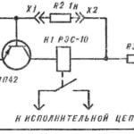 THE KEY TO THE LOCK — UP RESISTOR
In the fourth issue of the journal for the year 1978, published schemes of electric locks with a "secret". They all work well, but they, in my opinion, there is one drawback: the locks...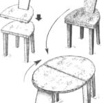 CHAIR? YES, AND THE TABLE
To the semi-circular platform on four legs is applied on top of the same with embedded in her Board-back: it turns out the chair. If we combine the above-mentioned half-hinges and...
